Booster pump with self pressure stabilizing performance

A booster pump and self-stabilizing technology, which is applied to pumps with flexible working elements, components of pumping devices for elastic fluids, pumps, etc., can solve the problem of no buffer zone for pressure relief and inconvenient disassembly and other problems, to achieve the effect of good circumferential sealing, convenient maintenance and reasonable structure

Inactive Publication Date: 2016-11-09
山东中聚电器有限公司
View PDF9 Cites 4 Cited by
  • Summary
  • Abstract
  • Description
  • Claims
  • Application Information

AI Technical Summary

Problems solved by technology

This invention has been optimized according to the space occupied by 200610104087.2, and the problems of large safety hazards in suspended conduits have been optimized, but its tunnel type has a 90-degree right-angle channel for water flow, and there are certain drawbacks and the end of the tunnel is blocked after installation. Fluid chamber screws cause inconvenient disassembly
[0005] The patent document with the application number 201320572586.X discloses a design scheme of a diaphragm pump pressure stabilization and pressure relief regulator, but the patent does not provide a buffer zone for the pressure relief pressure

Method used


Image

  • Booster pump with self pressure stabilizing performance
  • Booster pump with self pressure stabilizing performance
  • Booster pump with self pressure stabilizing performance

Examples


Embodiment Construction

[0020] Embodiments of the present invention will be further described in detail below in conjunction with the accompanying drawings.

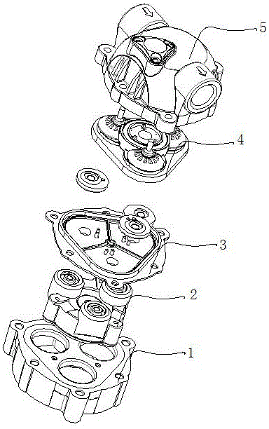
[0021] Such as figure 1 As shown, the present invention provides a booster pump with self-stabilizing performance, which includes a motor part and a pump head part. The front end of the motor part is provided with a pump head part. The water outlet is discharged. The pump head includes a fluid chamber bracket 1 fixed to the motor. The fluid chamber bracket is movably connected with the fluid chamber 5. A piston frame 2, a diaphragm 3 and a diaphragm chamber 4 are installed inside. The diaphragm chamber 4 is provided with several checks. valve.

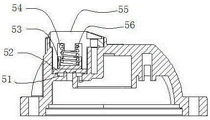
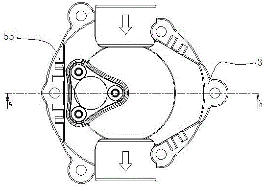
[0022] Such as Figure 2 to Figure 6 As shown, a pressure-stabilizing channel is provided between the upper part of the diaphragm chamber 4 and the fluid chamber, and the pressure-stabilizing channel communicates with the low-pressure chamber and the high-pressure chamber. Open and close valve, the s...


PUM


Abstract

The invention relates to the technical field of booster pumps for a reverse osmosis system, and provides a booster pump with a self pressure stabilizing performance. The booster pump comprises a motor part and a bump head part, wherein a pump head is internally provided with a piston frame, a diaphragm and a diaphragm chamber, a plurality of check valves are arranged on the diaphragm chamber, a pressure stabilizing passage is arranged between the upper part of the diaphragm chamber and a fluid chamber, and is used for communicating a low pressure chamber with a high pressure chamber, a valve used for controlling the open and closure of the pressure stabilizing passage is arranged on the fluid chamber and is located at one side of an axis of an water inlet and a water outlet; the valve comprises an outer ring rib and an inner ring rib which are located at the middle part, the inner side of the inner ring rib is provided with a buffer relief hole, a buffer water inlet is connected with a spirally ascending relief buffer area of which the tail end is in sealing connection with the buffer relief hole in a separable manner though a spring and valve block structure at the upper part. According to the booster pump, water of which the pressure excesses a setting pressure is split to the lower pressure chamber through a valve block by virtue of the pressure stabilizing passage, the safety of the whole device is ensured, the service life is prolonged, the vibration of a pump body is reduced, the valve block is in torus contact with the buffer relief area, so the circumferential sealing performance is good, and a relief process is stable.

Description

technical field [0001] The invention relates to the technical field of a booster pump used in a reverse osmosis system, in particular to a booster pump structure with a self-stabilizing function. Background technique [0002] With the continuous expansion of the market penetration rate of reverse osmosis water purifiers, the requirements for the use of environmental conditions have also become more extensive, and the requirements for the core component booster pump have also increased simultaneously. Several companies have already done this in this regard. Also invested technical force to optimize the original structure; [0003] For example, the patent document with application number 200610104087.2 discloses a design scheme of a constant pressure diaphragm pump. The main purpose of this invention is to provide a constant-pressure diaphragm pump, which is mainly provided with a communication pipeline between the water pressure discharge port and the water inlet of the pump...

Claims


Application Information

Patent Timeline
Patent Type & Authority Applications(China)
IPC IPC(8): F04B43/04F04B49/22F04B53/16F04B53/10
CPCF04B43/04F04B43/0009F04B43/0081F04B53/102F04B53/1087
Inventor 项树民虞召星
Owner 山东中聚电器有限公司
Why Eureka
Try Eureka