Horizontal multi-stage centrifugal pump

A centrifugal pump, horizontal technology, applied in the field of horizontal multi-stage centrifugal pumps, can solve the problems of different impellers at different levels, different flow losses, poor suction performance, etc., and achieve simple structure, extended service life, and easy manufacturing and maintenance effect

Inactive Publication Date: 2016-11-09
NORTH CHINA UNIV OF WATER RESOURCES & ELECTRIC POWER
View PDF7 Cites 8 Cited by
  • Summary
  • Abstract
  • Description
  • Claims
  • Application Information

AI Technical Summary

Problems solved by technology

[0004] The technical problem to be solved by the present invention is that the existing horizontal multistage centrifugal pump has poor suction performance and relatively large axial force. The resulting flow losses are different, r

Method used


Image

  • Horizontal multi-stage centrifugal pump
  • Horizontal multi-stage centrifugal pump

Examples


Embodiment Construction

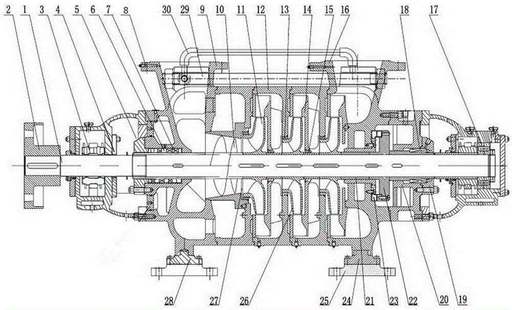
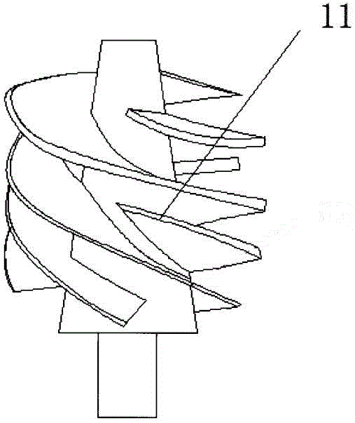
[0020] as attached Figure 1-2 As shown, a horizontal multi-stage centrifugal pump includes a pump body. A pump shaft 1 is installed in the pump body. The pump shaft 1 is connected to the prime mover through a coupling 2. The pump body includes a suction section 9 connected in sequence, a pumping Section 12 and pumping section 16, the pump shaft 1 is set in the suction section 9, pumping section 12 and pumping section 16, the suction section 9 is provided with a suction port, the pumping section 16 is provided with a discharge port, the suction port and the discharge port The outlets are all set up, and the pump shaft 1 in the pumping section 12 is equipped with an impeller, the impeller includes a first-stage impeller 11 installed on the pump shaft 1 close to the suction section 9, and several secondary impellers behind the first-stage impeller 11 26, the inducer 10 is installed on the pump shaft 1 close to the primary impeller 11 in the suction section 9, and the guide vane ...


PUM

PropertyMeasurementUnit
Thicknessaaaaaaaaaa
Thicknessaaaaaaaaaa

Abstract

The invention discloses a horizontal multi-stage centrifugal pump. The horizontal multi-stage centrifugal pump comprises a pump body; a pump shaft is mounted in the pump body, and is connected with a prime mover through a coupling; the pump body includes a sucking section, a pumping section and a pumping-out section which communicate with one another in sequence; the pump shaft is inserted in the sucking section, the pumping section and the pumping-out section; a sucking port is formed in the sucking section; a discharge port is formed in the pumping-out section; the sucking port and the discharge port are both upwards arranged; an impeller is mounted on the pump shaft in the pumping section, and includes a first-grade impeller mounted on the pump shaft near the sucking section and multiple secondary-grade impellers behind the first-stage impeller; an induction wheel is mounted on the pump shaft, near the first-stage impeller, in the sucking section; guide blades are mounted on one sides, near the pumping-out section, of the secondary-grade impellers; the guide blades are fixed on the pump shaft; and the outer diameters of the later-grade guide blades are 1.1-1.15 times of the outer diameters of the previous-stage guide blades. The horizontal multi-stage centrifugal pump is the same in designed flow of all stages of impellers and different in designed lift; and the lifts of the later-stage impellers are 1.05-1.15 times of the lifts of the previous-stage impellers, so that all stages of impellers can be synchronously kept in optimal working conditions, and the efficiency is improved.

Description

technical field [0001] The invention belongs to the technical field of fluid pumps, in particular to a horizontal multistage centrifugal pump. Background technique [0002] Horizontal multistage centrifugal pump has the characteristics of wide performance range, low noise, long life, convenient installation and maintenance, etc. It is used to transport clean water or other liquids with physical and chemical properties similar to water. It is mainly suitable for water supply and drainage of urban high-rise buildings and fire water, power plants. , factories, mine water supply and drainage, long-distance water delivery, water in the production process cycle, HVAC cycle, domestic water and other purposes. [0003] However, the existing horizontal multistage centrifugal pump has poor suction performance and large axial force. At the same time, the conventional multistage centrifugal pump has the same parameters such as the flow rate and lift of the impellers at all levels, but t...

Claims


Application Information

Patent Timeline
IPC IPC(8): F04D1/06F04D29/22F04D29/66
CPCF04D1/06F04D29/185F04D29/2222F04D29/225F04D29/2266F04D29/2272F04D29/2294F04D29/669
Inventor 何小可王为术马强
Owner NORTH CHINA UNIV OF WATER RESOURCES & ELECTRIC POWER
Why Eureka
Try Eureka