Stator blade driving device

A drive device, technology of stator blades, applied to components of pumping devices for elastic fluids, machines/engines, liquid fuel engines, etc.

Active Publication Date: 2016-11-09
AECC SHENYANG ENGINE RES INST
View PDF6 Cites 4 Cited by
  • Summary
  • Abstract
  • Description
  • Claims
  • Application Information

AI Technical Summary

Problems solved by technology

[0003] The purpose of the present invention is to provide a stator vane driving devi

Method used


Image

  • Stator blade driving device
  • Stator blade driving device

Examples


Embodiment Construction

[0018] In order to make the objectives, technical solutions and advantages of the present invention clearer, the technical solutions in the embodiments of the present invention will be described in more detail below in conjunction with the drawings in the embodiments of the present invention. In the drawings, the same or similar reference numerals denote the same or similar elements or elements having the same or similar functions throughout. The described embodiments are some, but not all, embodiments of the invention. The embodiments described below by referring to the figures are exemplary and are intended to explain the present invention and should not be construed as limiting the present invention. Based on the embodiments of the present invention, all other embodiments obtained by persons of ordinary skill in the art without creative efforts fall within the protection scope of the present invention. Embodiments of the present invention will be described in detail below ...


PUM


Abstract

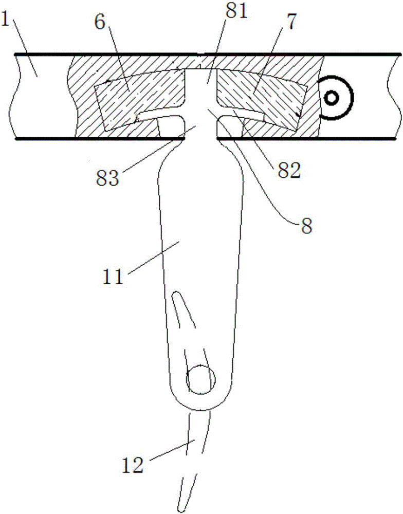
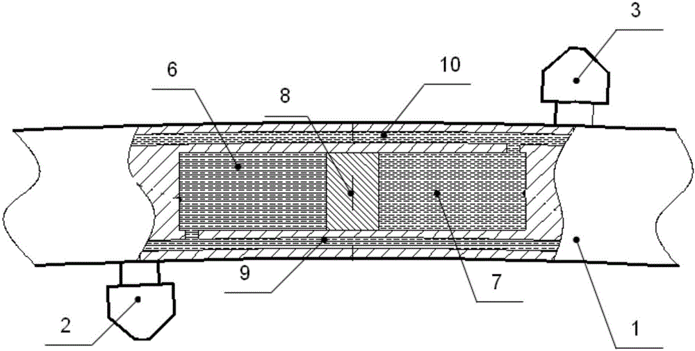
The invention discloses a stator blade driving device and relates to the technical field of turbine engines. The stator blade driving device is used for adjusting the installation angle of a blade and comprises a support and a rocker arm. The support is of an annular structure and is fixedly installed on a casing. An oil cavity is formed in the support. The oil cavity is an arc-shaped section. A piston is arranged in the oil cavity. The oil cavity is divided into a first oil cavity body and a second oil cavity body by the piston. The first oil cavity body is provided with a first oil nozzle. The second oil cavity body is provided with a second oil nozzle. One end of the piston stretches out of the oil cavity and is connected with one end of the rocker arm. The other end of the rocker arm is connected with the blade. The stator blade driving device has the beneficial effects that the driving rocker arm of the blade moves in the oil cavity in the support according to a preset path, the rocker arm is driven by the piston, the piston is driven by the pressure difference of the first oil cavity body and the second oil cavity body, the rocker arm is not affected by outside resistance, and the rocker arm is prevented from being deformed in the rotation process.

Description

technical field [0001] The invention relates to the technical field of turbine engines, in particular to a stator vane driving device. Background technique [0002] In order to pursue a larger stable working range in modern turbine engines, the annular and evenly distributed stator blades in the compressor are usually set to rotate around themselves. The currently known working angle adjustment mechanism of the stator vane includes a hydraulic cylinder, a control bracket, a "V" rocker arm, a connecting rod, a linkage ring and the like. The hydraulic actuator outputs linear motion, driving one end of the "V" rocker arm to rotate around the axis, and the other end of the "V" rocker arm drives the linkage ring through the connecting rod, and the linkage ring drives the rocker arm fixed to the blade, and then Drive the whole circle of blades to rotate. The blade rocker arm distributed in the whole circle rotates in the plane when it is working, which is inconsistent with the d...

Claims


Application Information

Patent Timeline
IPC IPC(8): F04D29/46F04D29/56
CPCF04D29/462F04D29/563
Inventor 马晓健王华韩方军赵晓东白志刚
Owner AECC SHENYANG ENGINE RES INST
Why Eureka
Try Eureka