
Tooth profile design method of three-dimensional high rigidity harmonic reducer

A technology of harmonic reducer and design method, applied in the direction of gear teeth, mechanical equipment, components with teeth, etc., can solve the problems of poor resistance to torsional deformation, small bearing capacity, short service life, etc. Torsional deformation ability, extended service life, effect of high load-carrying capacity

Active Publication Date: 2018-11-30
铂睿(山东)精密工业有限公司
View PDF10 Cites 0 Cited by
  • Summary
  • Abstract
  • Description
  • Claims
  • Application Information

AI Technical Summary

Problems solved by technology

[0006] In view of the above-mentioned defects or deficiencies in the prior art, it is desired to provide a tooth profile design method for a three-dimensional high-rigidity harmonic reducer to solve the problems in the prior art that the harmonic gear reducer has poor resistance to torsional deformation, load-carrying Small capacity, short service life and difficult gear processing

Method used


Image

  • Tooth profile design method of three-dimensional high rigidity harmonic reducer
  • Tooth profile design method of three-dimensional high rigidity harmonic reducer
  • Tooth profile design method of three-dimensional high rigidity harmonic reducer

Examples


Embodiment Construction

[0031] The application will be further described in detail below in conjunction with the accompanying drawings and embodiments. It should be understood that the specific embodiments described here are only used to explain related inventions, rather than to limit the invention. It should also be noted that, for ease of description, only parts related to the invention are shown in the drawings.

[0032] It should be noted that, in the case of no conflict, the embodiments in the present application and the features in the embodiments can be combined with each other. The present application will be described in detail below with reference to the accompanying drawings and embodiments.

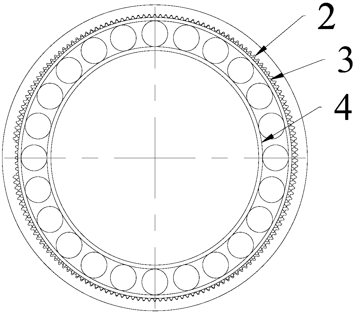
[0033] Please refer to figure 1 As mentioned above, the harmonic reducer obtained by implementing the tooth profile design method of the three-dimensional high-rigidity harmonic reducer provided by the embodiment of the present invention, wherein the harmonic reducer includes a wave generator 4, a...


PUM


Abstract

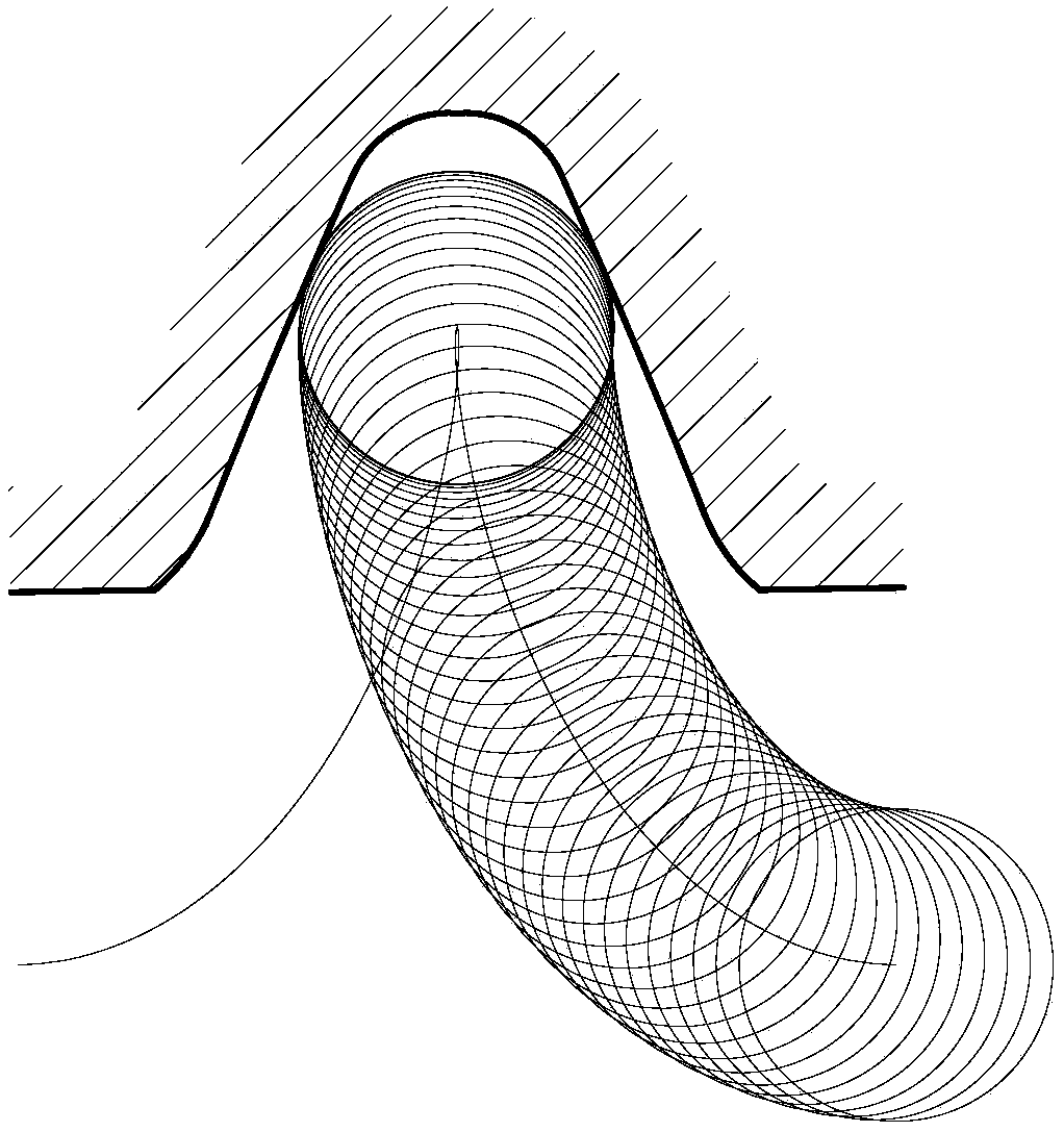
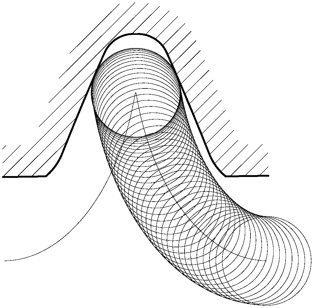
Disclosed is a tooth profile design method for a three-dimensional high-rigidity harmonic speed reducer. The harmonic speed reducer comprises a wave generator (4), a rigid gear (2) and a flexible gear (3). The rigid gear (2) is engaged with the flexible gear (3). The wave generator (4) is in contact with an inner wall of the flexible gear (3). Both the rigid gear (2) and the flexible gear (3) are involute gears. The tooth number of the rigid gear (2) is Z1, and the tooth number of the flexible gear (3) is Z2, where Z1 - Z2 = 2. The modification coefficient of the rigid gear (2) is x1, the modification coefficient of the flexible gear (3) is x2, where x1 < x2, and the modification difference is Δx = x1 - x2. Material removing and profile modification are performed on two sides or the top of the addendum circle of the rigid gear (2) and / or the flexible gear (3). The implementation of the tooth profile design method is convenient, the machining cost is lower, the purpose of large-area engagement is achieved, the torsional deformation resistance and bearing capacity of the harmonic speed reducer are improved, and the service life of the harmonic speed reducer is prolonged.

Description

technical field [0001] The present application generally relates to the technical field of harmonic reducers, and in particular to a tooth profile design method of a three-dimensional high-rigidity harmonic reducer. Background technique [0002] Rigidity is an important index to evaluate the performance of the harmonic gear reducer. Good rigidity means that the harmonic gear reducer has good resistance to torsional deformation, large carrying capacity and long service life. [0003] At present, there are mainly the following methods for improving the rigidity of the harmonic gear reducer: [0004] (1) Improve the gear strength by changing the gear material. Chinese patent document CN201180014539.7 discloses a technical solution for improving the strength of the gear by heat-treating the flexspline of the harmonic gear reduction device to change the metal crystal phase structure. Chinese patent document CN201410372571.8 discloses that by changing the composition and ratio o...

Claims


Application Information

Patent Timeline
Patent Type & Authority Patents(China)
IPC IPC(8): F16H55/08B23F21/04B23F21/16
CPCF16H55/08
Inventor 吴文
Owner 铂睿(山东)精密工业有限公司
Learn More