

Three-stage stratified combustion high temperature rise combustion chamber structure
A stratified combustion and combustion chamber technology, applied in combustion chambers, continuous combustion chambers, combustion methods, etc., can solve problems such as large head air flow, difficult main combustion stage flames, and high temperature rise combustion chamber combustion stability problems. To achieve the effect of improving stability, improving combustion stability and improving flame stability
- Summary
- Abstract
- Description
- Claims
- Application Information
AI Technical Summary
Problems solved by technology
Method used
Image

Examples
Embodiment Construction
[0043] In order to make the object, technical solution and advantages of the present invention clearer, the present invention will be further described in detail below with reference to the accompanying drawings and examples. It should be noted that the following descriptions are only preferred embodiments of the present invention, and therefore do not limit the protection scope of the present invention.
[0044] It should be noted that implementations not shown or described in the accompanying drawings are forms known to those of ordinary skill in the art. In addition, the directional terms mentioned in the following embodiments, such as "upper", "lower", "front", "backward", "left", "right", "top", "bottom", etc., are only for reference The orientation of the graph. Accordingly, the directional terms are used to illustrate and not to limit the invention.
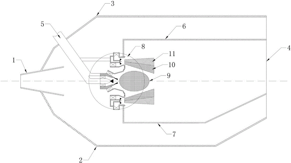
[0045] Such as figure 1 As shown, the high-temperature rising combustor structure of the three-stage stratified combu...
PUM
| Property | Measurement | Unit |
|---|---|---|
| Diameter | aaaaa | aaaaa |
Abstract
Description
Claims
Application Information