Profile detection device used for automobile parts

A technology for auto parts and surface detection, applied in the direction of measuring devices, mechanical devices, mechanical measuring devices, etc., can solve the problems of increasing the difficulty of detection, time-consuming detection, reading errors, etc., to ensure high-precision detection, convenient radius, The effect of detecting convenience

Active Publication Date: 2016-11-09
KUNSHAN DAYA AUTO PARTS
View PDF6 Cites 0 Cited by
  • Summary
  • Abstract
  • Description
  • Claims
  • Application Information

AI Technical Summary

Problems solved by technology

At present, vernier calipers, micrometers, and three-coordinate measurements are generally used to control product size, but these detection methods are time-consuming, costly in terms of financial and human resources, an

Method used


Image

  • Profile detection device used for automobile parts
  • Profile detection device used for automobile parts
  • Profile detection device used for automobile parts

Examples


Embodiment 1

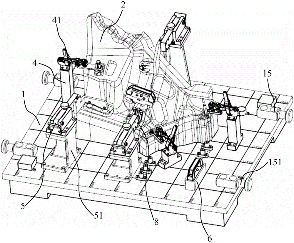
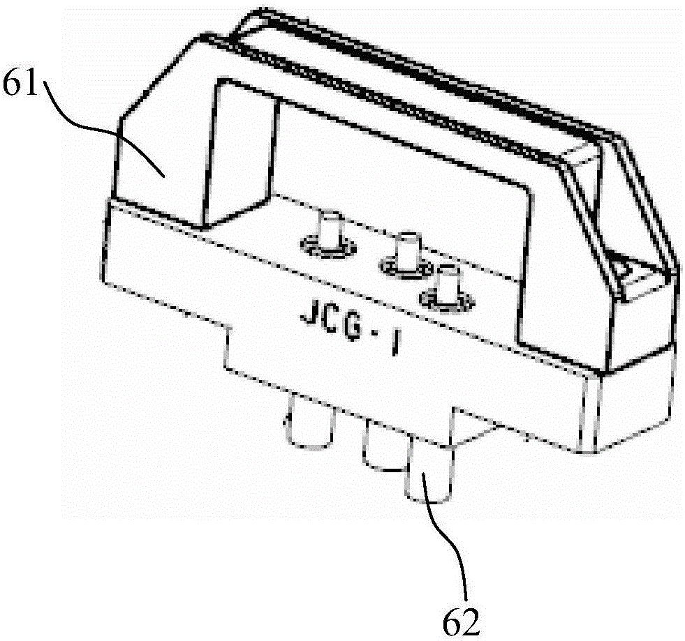
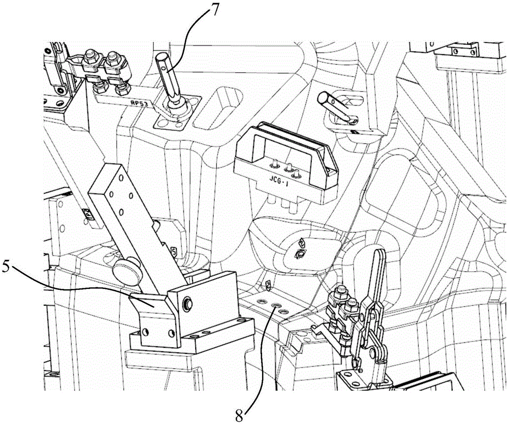
[0027] Embodiment 1: A surface detection device for automobile parts, comprising a coordinate base 1, an analog block seat for placing the parts to be tested, a detection rod 3, at least two clamping mechanisms 4, and at least two gap detection mechanisms 5 The through hole position detection mechanism 6 and the through stop gauge pin 7, the clamping mechanism 4 and the gap detection mechanism 5 are installed on the coordinate base 1, and the clamp 41 located at the upper end of the clamping mechanism 4 is used to clamp and place the analog block For the parts to be tested on the upper surface of the base 2, the through-hole position detection mechanism 6 further includes a handle base 61 and at least two second pins 62 on the bottom surface of the handle base 61;

[0028] The lower part of the through-stop gauge plug 7 is a first latch 71. The middle part of the through-stop gauge plug 7 is provided with a through-regulation part 72 and a regulation-stop part 73 from bottom to to...

Embodiment 2

[0033] Embodiment 2: A surface inspection device for automobile parts, comprising a coordinate base 1, an analog block seat for placing the parts to be inspected 2, a detection rod 3, at least 2 clamping mechanisms 4, and at least 2 gap inspection mechanisms 5 The through hole position detection mechanism 6 and the through stop gauge pin 7, the clamping mechanism 4 and the gap detection mechanism 5 are installed on the coordinate base 1, and the clamp 41 located at the upper end of the clamping mechanism 4 is used to clamp and place the analog block For the parts to be tested on the upper surface of the base 2, the through-hole position detection mechanism 6 further includes a handle base 61 and at least two second pins 62 on the bottom surface of the handle base 61;

[0034] The lower part of the through-stop gauge plug 7 is a first latch 71. The middle part of the through-stop gauge plug 7 is provided with a through-regulation part 72 and a regulation-stop part 73 from bottom to...


PUM


Abstract

The invention discloses a profile detection device used for automobile parts A clamping mechanism and a gap detecting mechanism are disposed on a coordinate base, and a clamp disposed on the upper end of the clamping mechanism is used for clamping a to-be-detected part disposed on an upper surface of a simulation block base. A lower part of a latch of a go/no go gauge is a first latch, and the middle part of the latch of the go/no go gauge is, from bottom to top, provided with a go gauge part and a no go gauge part sequentially, and the upper part of the go/no go gauge is a push rod part. The gap detecting mechanism further comprises a base, a clamping board; a left fixing board and a right fixing board, which are parallely disposed on the upper surface of the base; and a rotating arm, the rear end of which is disposed between the left fixing board and the right fixing board. The clamping board is disposed on the front end of the rotating arm, and four corners of the coordinate base are respectively provided with a hoisting rod. The profile detection device used for the automobile parts is advantageous in that the gaps between the parts are detected quickly and visually, and the reliability of the detection is high, the efficiency of the detection is high, and whether the parts are qualified is determined quickly and visually.

Description

Technical field [0001] The invention relates to a shape detection device for automobile parts, belonging to the technical field of automobile parts detection. Background technique [0002] With the development of the automobile industry, on the one hand, it is required to accurately control the product size during the development, manufacturing and inspection of automobiles, and on the other hand, the control method is required to be convenient, fast, intuitive, accurate, and efficient. At present, vernier calipers, micrometers, and three-coordinates are commonly used to control the size of products. However, these detection methods have problems such as time-consuming detection, high financial and human resources, and reading errors that vary from person to person. In addition, the irregular size of the product cannot be measured with vernier calipers and micrometers, which increases the difficulty of detection. Summary of the invention [0003] The object of the present inventi...

Claims


Application Information

Patent Timeline
IPC IPC(8): G01B5/00G01B5/14G01B5/08
CPCG01B5/0025G01B5/08G01B5/14
Inventor 王飞孟悦娟杨为
Owner KUNSHAN DAYA AUTO PARTS
Why Eureka
Try Eureka