Self-calibration measurement device and method for bridge deformation or displacement parameters

A measuring device and self-calibration technology, applied in the field of mechanical measurement, can solve problems such as increasing system complexity and affecting measurement accuracy, and achieve the effects of convenient application, improved measurement accuracy, and compact and reliable structure

Active Publication Date: 2016-11-09
西安敏文测控科技有限公司
View PDF8 Cites 26 Cited by
  • Summary
  • Abstract
  • Description
  • Claims
  • Application Information

AI Technical Summary

Problems solved by technology

The main problem with this type of displacement sensor at present is that the CCD image sensor needs to be used in conjunction with a collimated laser, which increases the complexity of the system
The problem with this solution is that it is limited by the construction conditions. The CCD camera is usually fixed on the bridge body of the bridge, so the position of the CCD is also deformed with the change of the external environment and stress load, especially because the measurement target and the CCD The camera is installed at a certain distance. When the load-carrying vehicle drives to the middle of the bridge, the entire bridge will bend and deform, causing the CCD camera to generate an inclination angle relative to the horizontal direction. This inclination angle will be enlarged when imaging the measurement target set at a long distance For a large displacement, a system background error is superimposed on the measured parameter result, which greatly affects the measurement accuracy

Method used


Image

  • Self-calibration measurement device and method for bridge deformation or displacement parameters
  • Self-calibration measurement device and method for bridge deformation or displacement parameters
  • Self-calibration measurement device and method for bridge deformation or displacement parameters

Examples


Embodiment Construction

[0035] When the imaging method is used for bridge displacement monitoring, the CCD camera is usually installed in a small displacement area, but when the load vehicle 19 travels to the middle of the bridge, the entire bridge will be bent and deformed, causing the CCD camera to generate an inclination angle relative to the horizontal direction , the inclination angle will be magnified into a large displacement when imaging the measurement target set at a long distance, thus superimposing a system background error on the measured parameter results, which greatly affects the measurement accuracy.

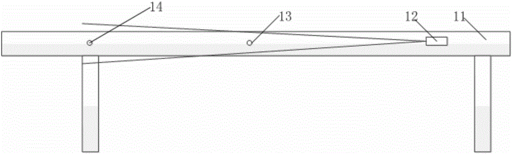
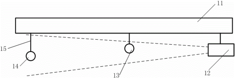
[0036] Such as figure 1 As shown, the present invention is used for the self-calibrating measuring device of bridge deformation or displacement parameters, including imaging system 12, no less than one measurement target 13 installed on the bridge measurement point, and deformation or displacement change installed on the bridge The reference target 14 in the negligible area, the refere...


PUM


Abstract

The invention discloses a self-calibration measurement device for bridge deformation or displacement parameters, comprising an imaging system (12) and at least one measurement target (13) installed at a measurement point of a bridge (11). The self-calibration measurement device is characterized in that the device further comprises a benchmark target (14) installed in a deformation or displacement change-negligible region of the bridge (11), the benchmark target (14) and the measurement target (13) are imaged in different positions of a sensitive element of the imaging system (12), and the displacement or deformation parameters of the measurement point are calculated according to the measurement results of the measurement target (13) and the benchmark target (14) after the influence of bridge bending deformation caused by load loading is deducted. As the influence of bridge bending deformation caused by load loading is deducted, the measurement accuracy of the system is improved.

Description

technical field [0001] The invention belongs to the technical field of mechanical measurement, and relates to a bridge displacement and deformation measurement device, in particular to a self-calibrating remote displacement or deformation measurement device and method. Background technique [0002] Bridge deformation mainly includes static deformation and dynamic deformation. Static deformation refers to deformation that changes very slowly, such as foundation subsidence, inclination, and stress relaxation. Dynamic deformation refers to short-term deformation caused by wind, temperature, earthquake, traffic load or on-site construction. Its parameter monitoring plays an important role in the security assessment and analysis of the target. [0003] For traditional bridges such as bridges, the instruments for deformation detection include dial gauges, dial gauges, accelerometers, levels, and theodolites. At present, these instruments are still widely used in bridge acceptance...

Claims


Application Information

Patent Timeline
Patent Type & Authority Applications(China)
IPC IPC(8): G01B11/02G01B11/16
CPCG01B11/02G01B11/16
Inventor 屈战辉高文武
Owner 西安敏文测控科技有限公司
Why Eureka
Try Eureka