Fan rotating speed control system and method for electric vehicle battery charger

A fan speed and control system technology, applied in engine control, pump control, machine/engine, etc., can solve problems such as inaccurate measurement, inconsistent fan speed, nonlinear resistance-temperature curve, etc.

Active Publication Date: 2016-11-16
CHINA ELECTRIC POWER RES INST +1
View PDF8 Cites 9 Cited by
  • Summary
  • Abstract
  • Description
  • Claims
  • Application Information

AI Technical Summary

Problems solved by technology

[0004] After the over-temperature alarm of the charging module, it is necessary to manually find the fan that is stalled or the speed is too low, and then replace it; the fan is jammed or the input voltage is low, which can cause the fan to stop or the speed is too low, and the speed of the fan cannot be checked visually. In addition, it cannot be measured accurately, which leads to over-reliance on experience in the process of dealing with fan failures, and it is difficult to avoid deviations in the identification of failed fans
[0005] The temperature of the power device in the charging module is measured by the core processor through the temperature measuring element, which usually uses a thermistor; the consistency of the thermistor temperature measuring element is very poor, and the resistance-temperature curve has serious nonlinearity ;Due to the inconsistency of temperature measurement data, the speed of the fans in each charging module cannot be unified. Because there is a current equalization circuit between each charging module, the output power of each charging module is basically the same, which eventually causes some charging modules to run at high temperature for a long time , premature failure

Method used


Image

  • Fan rotating speed control system and method for electric vehicle battery charger
  • Fan rotating speed control system and method for electric vehicle battery charger
  • Fan rotating speed control system and method for electric vehicle battery charger

Examples


Embodiment Construction

[0121] In order to better understand the present invention, the content of the present invention will be further described below in conjunction with the accompanying drawings.

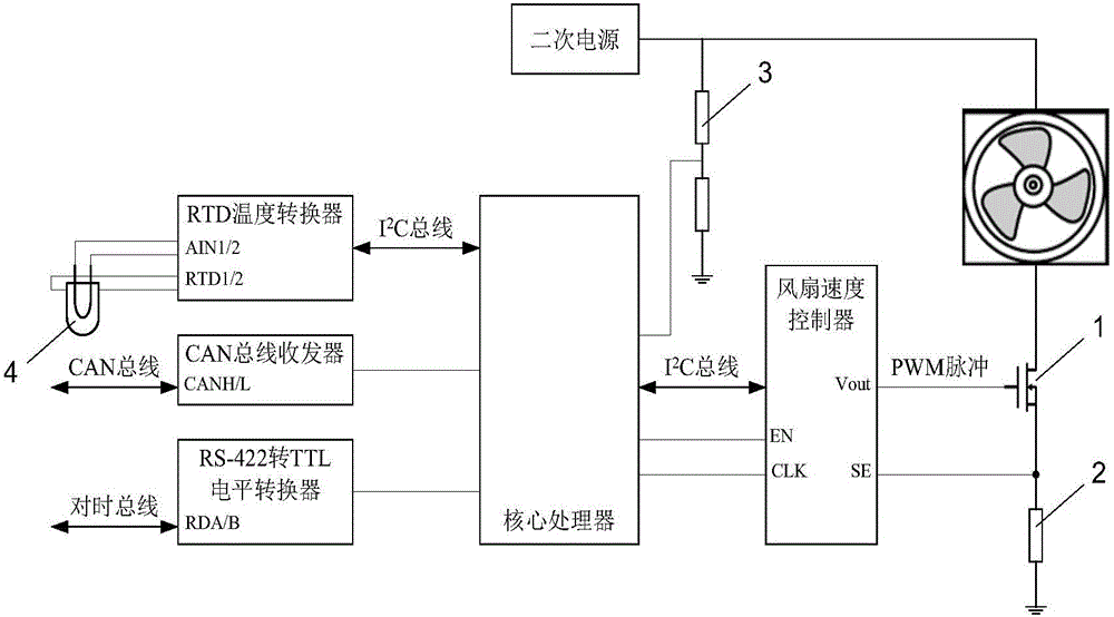
[0122] Such as figure 1 The fan speed control system shown in the first embodiment of the present invention is located in a charging module, including a fan control unit, a fan and a temperature measurement unit; the fan control unit includes a fan speed control circuit, a fan input voltage measurement circuit Rotate the control circuit synchronously with the fan.

[0123] The fan speed control system should share the core processor and CAN bus communication circuit with other control systems in the charging module.

[0124] The charging module core processor has the following technical details:

[0125] The core processor adopts a digital signal processor (DSP), and the DSP chip has powerful mathematical operation capabilities, and has a wealth of on-chip peripherals and interfaces, including CAN bu...


PUM


Abstract

The invention provides a fan rotating speed control system for an electric vehicle battery charger. The fan rotating speed control system comprises a control device and charging modules, wherein the control device and the charging modules are connected through a CAN bus. Relevant parts in each charging module of the fan rotating speed control system comprise a core processor, a CAN bus communication circuit, a fan control unit, fans and a temperature measuring unit, wherein the fan control unit is connected with the fans through fan power input circuits correspondingly and connected with the temperature measuring unit and the CAN bus communication circuit through the core processor. According to the technical scheme provided by the invention, the stability of the rotating speed of the fans is enhanced, fan operating noise is lowered, and the fan fault diagnosis accuracy is improved.

Description

technical field [0001] The invention relates to the speed control of a fan, in particular to a fan speed control system and a control method for an electric vehicle charger. Background technique [0002] The electric vehicle charger adopts a modular configuration. Under the monitoring of the control device, multiple charging modules of the same type in the cabinet operate in parallel; the charging module is air-cooled, and the air inlet is equipped with a fan. Enter, pass through the internal air duct, and be discharged from the air outlet on the back panel of the charging module; the fan adopts a conventional 2-wire brushless DC fan, and the fan speed is controlled by the core processor in the charging module according to the heat sink of the power device in the charging module. The temperature is controlled, and the speed of the fan is generally divided into 2 to 3 gears; the control method of the fan is a simple open-loop control, and the core processor cannot know the fa...

Claims


Application Information

Patent Timeline
Patent Type & Authority Applications(China)
IPC IPC(8): F04D27/00H05K7/20
CPCF04D27/004F04D27/008F05D2270/303F05D2270/304H05K7/20209
Inventor 赵梦欣余伟成田阳刁晓虹郭媛媛劳斯佳刘洋赵晖
Owner CHINA ELECTRIC POWER RES INST
Why Eureka
Try Eureka