Liquid crystal lens and 3D displayer

A 3D display and liquid crystal lens technology, which is applied in the direction of instruments, optics, electrical components, etc., can solve the problems of reduced contrast, high brightness in the dark state, and large thickness of the liquid crystal layer of the liquid crystal lens, so as to increase the contrast of the screen and enhance the display effect , Reduce the effect of reflected light intensity

Active Publication Date: 2016-11-09
WUHAN CHINA STAR OPTOELECTRONICS TECH CO LTD
View PDF5 Cites 5 Cited by
  • Summary
  • Abstract
  • Description
  • Claims
  • Application Information

AI Technical Summary

Problems solved by technology

However, in the actual design process, due to the large thickness of the liquid crystal layer of the liquid crystal lens, it is necessary to use a larger spacer to support the thickness of the liquid crystal cell
The spherical spacer has a certain influence on the outgoing direction of the light emitted by the display panel, thereby changing the light intensity distribution in different directions in the viewing area, which will lead to a decrease in the contrast of the display effect and deterioration of the color. The larger the size, the more serious the impact
Especially in the case of dark state display, when there is strong external light reflection, the spacers will form obvious bright spots on the reflected light, resulting in high brightness in dark state, reducing contrast and affecting the overall 3D display effect

Method used


Image

  • Liquid crystal lens and 3D displayer
  • Liquid crystal lens and 3D displayer
  • Liquid crystal lens and 3D displayer

Examples


Embodiment Construction

[0024] The following will clearly and completely describe the technical solutions in the embodiments of the present invention with reference to the accompanying drawings in the embodiments of the present invention. Obviously, the described embodiments are only part of the embodiments of the present invention, not all of them. Based on the embodiments of the present invention, all other embodiments obtained by persons of ordinary skill in the art without making creative efforts belong to the protection scope of the present invention.

[0025] In addition, the following descriptions of the various embodiments refer to the attached drawings to illustrate specific embodiments in which the present invention can be implemented. The directional terms mentioned in the present invention, for example, "upper", "lower", "front", "rear", "left", "right", "inner", "outer", "side", etc., only is to refer to the direction of the attached drawings. Therefore, the direction terms used are for ...


PUM

PropertyMeasurementUnit
reflectanceaaaaaaaaaa

Abstract

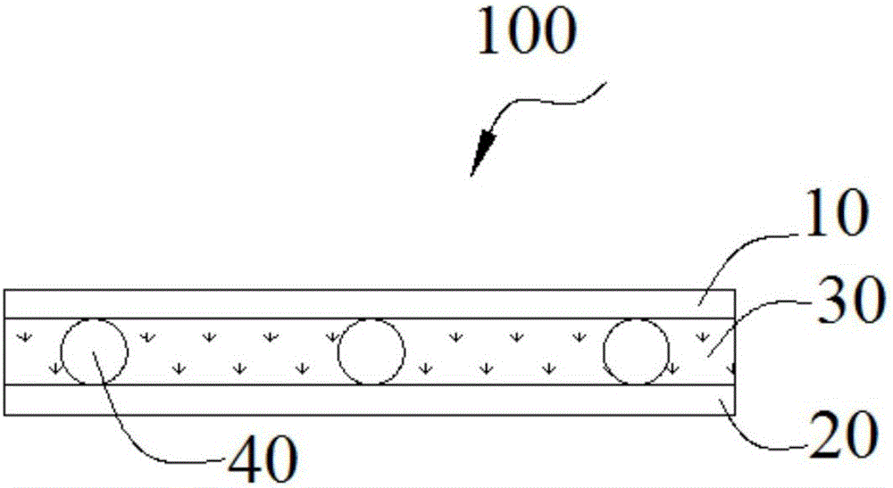
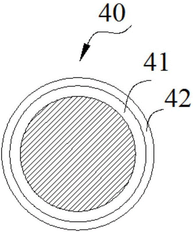
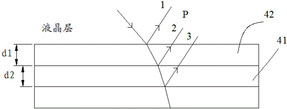
The invention provides a liquid crystal lens. The liquid crystal lens comprises an upper substrate, a lower substrate, a liquid crystal layer and spacers, wherein the liquid crystal layer and the spacers are arranged between the upper substrate and the lower substrate. The surface of each spacer is coated with a first antireflective film and a second antireflective film in sequence. The refractive index of the liquid crystal layer is n0, the refractive index of each first antireflective film is n2, the thickness of each first antireflective film is d2, the refractive index of each second antireflective film is n1, the thickness of each second antireflective film is d1, the refractive index of each spacer is n3, and then an equation shown in the description and the equation n1d1=n2d2=lambda/6 can be obtained, wherein lambda represents light wavelength. According to the liquid crystal lens and a 3D displayer, the intensity of reflected light on the spacers can be reduced, the contrast ratio of frames can be increased, and the display effect can be enhanced.

Description

technical field [0001] The invention belongs to the technical field of stereoscopic display, and in particular relates to a liquid crystal lens and a 3D display with the liquid crystal lens. Background technique [0002] Glasses-free 3D display technology can realize the effect of 3D images when viewing text and pictures without using special glasses, making the technology closer to users' daily habits. Therefore, glasses-free 3D display technology has also become a future development trend. [0003] The liquid crystal lens is applied in the field of naked-eye 3D display, and it has the advantages of simple control, strong reliability and low driving voltage, and has huge potential application. However, in the actual design process, since the thickness of the liquid crystal layer of the liquid crystal lens is relatively large, it is necessary to use a larger spacer to support the thickness of the liquid crystal cell. The spherical spacer has a certain influence on the outgo...

Claims


Application Information

Patent Timeline
Patent Type & Authority Applications(China)
IPC IPC(8): G02F1/29G02F1/1339G02F1/1335G02B1/113G02B27/22G02B30/28
CPCG02B1/113G02F1/133504G02F1/13392G02F1/29G02B30/28G02F1/133526G02F1/13471H04N13/302G02F2201/38G02F1/13398G02B30/27
Inventor 谢畅
Owner WUHAN CHINA STAR OPTOELECTRONICS TECH CO LTD
Why Eureka
Try Eureka