
Clapper type relay

A relay and snap-fit ​​technology, applied in the direction of relays, electromagnetic relays, detailed information of electromagnetic relays, etc., can solve problems such as unusable high-voltage fields, limited use occasions, and burnt-out of snap-fit ​​relays, so as to avoid fire and explosion accidents and break quickly , The effect of rapid breaking of dynamic and static contacts

Inactive Publication Date: 2016-11-09
ZHEJIANG YINGLUOHUA NEW ENERGY TECH CO LTD
View PDF8 Cites 4 Cited by
  • Summary
  • Abstract
  • Description
  • Claims
  • Application Information

AI Technical Summary

Problems solved by technology

The base and plastic insulation block of the existing snap-in relays are easy to be ignited by the arc generated by the passive static contact breaking, which can only reach about 450V, which limits the use of the existing snap-in relays and cannot be used in high-voltage fields ( The DC voltage is higher than 450V), and the snap-in relays used in new energy vehicles and buses have the risk of being burned

Method used


Image

  • Clapper type relay
  • Clapper type relay
  • Clapper type relay

Examples


Embodiment Construction

[0026] The present invention will be further described below in conjunction with the accompanying drawings and specific embodiments.

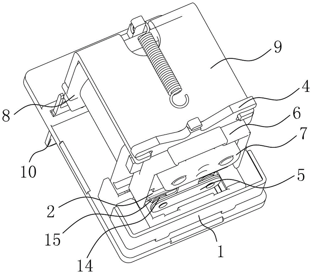
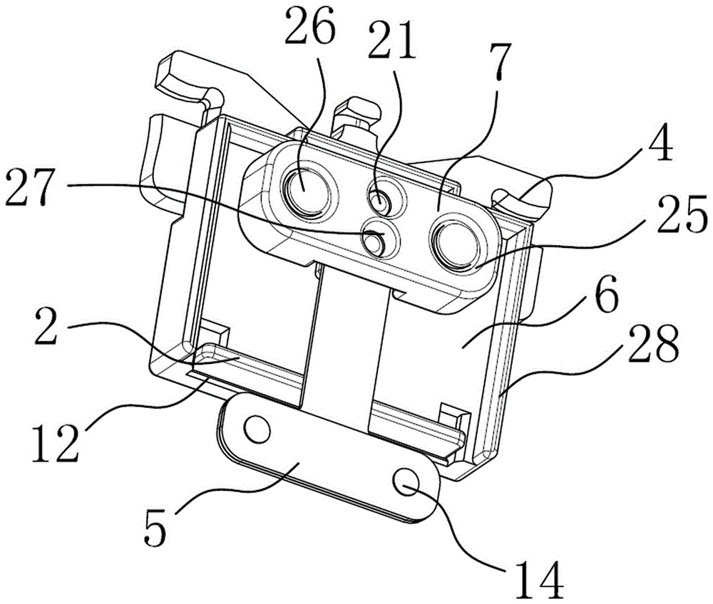
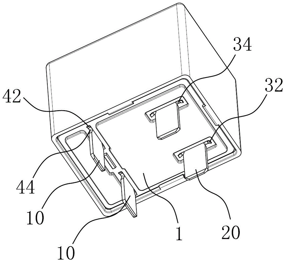
[0027] Depend on figure 1 , figure 2 , Figure 4 As shown, a snap-in relay of the present invention includes a base 1 made of ceramic material, a magnetic circuit part and a contact part, the magnetic circuit part includes a coil, an armature 4, an iron core and a yoke 9; the contact part includes a moving The contact assembly and the static contact assembly, the coil, the iron core and the yoke 9 are fitted together to form the coil part, the coil part, the moving contact assembly and the static contact assembly are installed on the upper side of the base, and the moving contact assembly It includes a moving contact 14, the static contact assembly includes a static contact 15, and the upper side of the joint of the moving and static contacts is provided with an upper insulating arc stop piece 2 made of ceramic material, and the moving conta...


PUM


Abstract

The invention discloses a snap-in relay, which comprises a base, a moving contact assembly and a static contact assembly are arranged on the upper side of the base, the moving contact assembly includes a moving contact, and the static contact assembly includes a static contact point, the upper side of the dynamic and static contacts is provided with an upper insulating arc-stopper, the base and the upper insulating arc-stopper are made of ceramic materials; the movable contact includes a left movable contact and a right movable contact, the The static contact includes a left static contact and a right static contact. The upper insulating arc stopper is located on the upper side of the junction of the moving and static contacts. The length of the upper insulating arc stopper is greater than the outer edge of the left moving contact and the The maximum distance between the outer edges of the right movable contacts may be greater than the maximum distance between the outer edges of the left static contacts and the right static contacts, and the width of the upper insulating arc shield is greater than the distance between the movable and static contacts.

Description

technical field [0001] The invention relates to the technical field of relays, in particular to a snap-in relay. Background technique [0002] The snap-in relay includes a base made of plastic material, a moving contact assembly and a static contact assembly. The moving contact assembly includes a moving reed, an armature and a plastic insulating block between the moving reed and the armature. The moving reed moves with the armature. Operation, the base is fixed with a load lead-out pin, the upper part of the load lead-out pin is located on the upper side of the base and is fixed with a static contact, the movable contact is located at the lower end of the movable reed, and the joint of the dynamic and static contact is located on the lower side of the plastic insulating block. The base and plastic insulation block of the existing snap-in relays are easy to be ignited by the arc generated by the passive static contact breaking, which can only reach about 450V, which limits t...

Claims


Application Information

Patent Timeline
Patent Type & Authority Applications(China)
IPC IPC(8): H01H50/54H01H50/64H01H9/34
CPCH01H50/54H01H9/34H01H50/64
Inventor 郭晓滨黄海燕杜德进
Owner ZHEJIANG YINGLUOHUA NEW ENERGY TECH CO LTD
Learn More