BMU installing support, power battery pack and electric automobile

A technology for power battery packs and mounting brackets, applied to battery circuit devices, secondary batteries, power devices, etc., can solve problems such as low installation and disassembly efficiency, affecting productivity, troubles, etc., to improve work and production efficiency, structure Simple, easy-to-operate effects

Active Publication Date: 2016-11-09
BEIJING PRIDE NEW ENERGY BATTERY
View PDF3 Cites 5 Cited by
  • Summary
  • Abstract
  • Description
  • Claims
  • Application Information

AI Technical Summary

Problems solved by technology

my country is currently in the period of vehicle energy conversion, and new energy vehicles are increasing day by day. In major enterprises, the production efficiency of battery modules and power battery packs in new energy vehicles determines the level of production efficiency. Most of the existing power battery packs have two or three layers, and each layer is equipped with a BMU (battery management unit) in the box. When it is necessary to install or repair the BMU, especially the middle and lower layers, due to It will be very troublesome to disassemble the entire cabinet and then remove the BMU. The existing method is to have a BMU entrance and exit at the front of each layer of the cabinet, and the BMU can be put in and out from this entrance. However, the BMU is currently installed in the box. The body is fixed using four bolts. When it needs to be taken out, four bolts need to be disassembled to take it out. The same is true for installation, and four bolts need to be tightened. Although this method has improved productivity, it has Because there are many bolts to be fastened, it is still relatively cumbersome, and the efficiency of installation and disassembly is not high, which still becomes a problem affecting productivity

Method used


Image

  • BMU installing support, power battery pack and electric automobile
  • BMU installing support, power battery pack and electric automobile
  • BMU installing support, power battery pack and electric automobile

Examples


Embodiment Construction

[0030] The principles and features of the present invention will be described below with reference to the accompanying drawings. The examples cited are only used to explain the present invention, and are not used to limit the scope of the present invention.

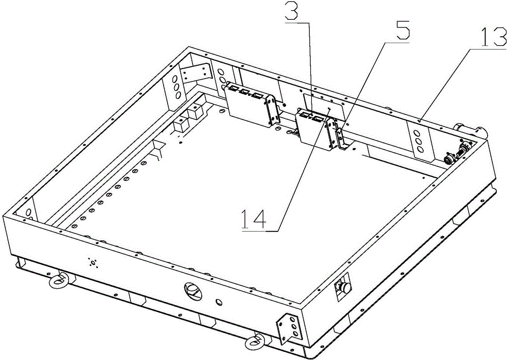
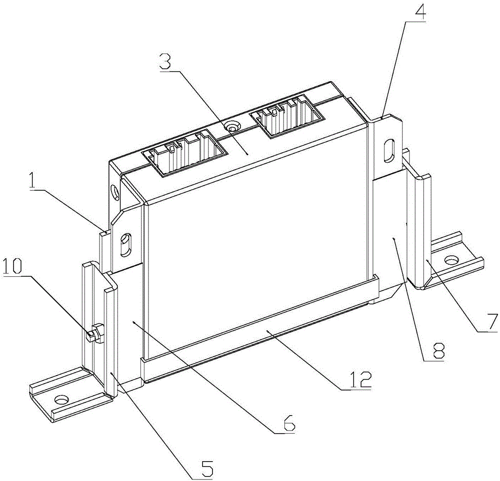
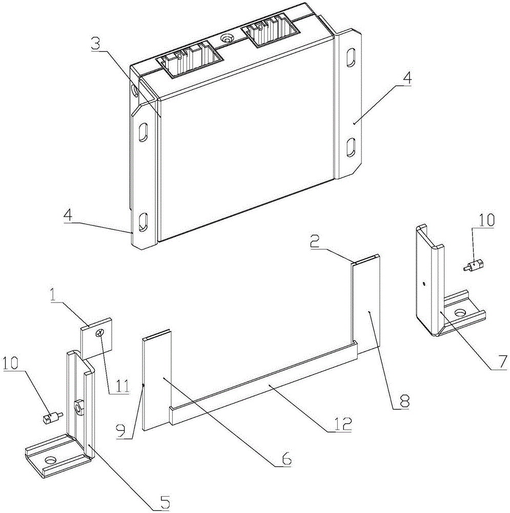
[0031] Such as Figure 1 to 4 As shown, figure 1 It is a schematic diagram of the overall structure of a BMU mounting bracket provided by the present invention after being installed in a power battery pack; figure 2 It is a schematic diagram of assembly of a BMU mounting bracket and BMU provided by the present invention; image 3 It is a schematic diagram of the disassembly structure of the BMU mounting bracket and the BMU provided by the present invention; Figure 4 It is a schematic diagram of assembly of a BMU mounting bracket provided by the present invention.

[0032] In a specific embodiment of a BMU mounting bracket provided by the present invention, the BMU mounting bracket includes a first sliding seat, a second slidi...


PUM


Abstract

The invention provides a BMU installing support used for installing a BMU. The BMU installing support comprises a first sliding base, a second sliding base and fixing plates, the first sliding base and the second sliding base are each provided with a sliding groove in the vertical direction, the sliding groove of the first sliding base and the sliding groove of the second sliding base are arranged oppositely, and the opening width of the sliding grooves is adaptive to the thickness of installing plates at the two sides of the BMU; the fixing plates are arranged on the upper portion of the first sliding base and/or the upper portion of the second sliding base, and the BMU can be fixedly connected with the fixing plates. The support is simple in structure, convenient to install and easy to operate, the BMU can be assembled or disassembled just by fastening or disassembling one or two bolts in the installing and overhaul process, operation is convenient and fast, and the work and production efficiency is greatly improved. The invention further provides a power battery pack and an electric automobile.

Description

Technical field [0001] The invention relates to the field of electric vehicles, in particular to a BMU mounting bracket, a power battery pack and an electric vehicle. Background technique [0002] At present, the global automobile industry is facing huge challenges in energy and environmental issues; pure electric vehicles with high energy efficiency and no pollution to the environment have increasingly become the development direction of the future automobile industry. China is currently in the period of vehicle energy conversion. New energy vehicles are currently increasing. In major enterprises, the production efficiency of battery modules and power battery packs in new energy vehicles has increased, which determines the level of production efficiency. In the existing power battery packs, most of them have two or three layers. Each layer is equipped with a BMU (Battery Management Unit) in the box. When the BMU needs to be installed or repaired, especially the middle and lower ...

Claims


Application Information

Patent Timeline
Patent Type & Authority Applications(China)
IPC IPC(8): H01M2/10H01M10/42B60K1/04
CPCB60K1/04H01M10/4257H01M2010/4271H01M50/20Y02E60/10
Inventor 李鸿键王小龙单长征杨振忠盛力杨槐宋春红
Owner BEIJING PRIDE NEW ENERGY BATTERY
Why Eureka
Try Eureka