Small frequency scanning horn antenna based on microstrip array feed

A technology of microstrip array and horn antenna, applied in the fields of microwave antenna, radar and wireless communication, can solve the problems of large antenna size and reduce the size of the horn antenna, and achieve the effect of reducing the size, shortening the length of the horn, and reducing the size

Active Publication Date: 2016-11-09
XIDIAN UNIV
View PDF5 Cites 21 Cited by
  • Summary
  • Abstract
  • Description
  • Claims
  • Application Information

AI Technical Summary

Problems solved by technology

[0005] The present invention provides a miniaturized frequency-swept horn antenna based on microstrip array feeding. By using a microstrip array instead of a rectangular waveguide to feed the horn structure, the size of the horn antenna can be effectively reduced under the premise of ensuring the same gain. It solves the problem that the size of the high-gain horn antenna is too large in the prior art, and at the same time, the frequency scanning function of the horn antenna can be realized by constructing a feeding structure of multiple sets of microstrip arrays

Method used


Image

  • Small frequency scanning horn antenna based on microstrip array feed
  • Small frequency scanning horn antenna based on microstrip array feed
  • Small frequency scanning horn antenna based on microstrip array feed

Examples


Embodiment 1

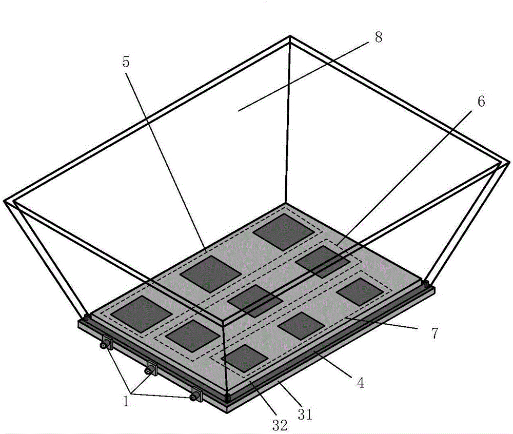
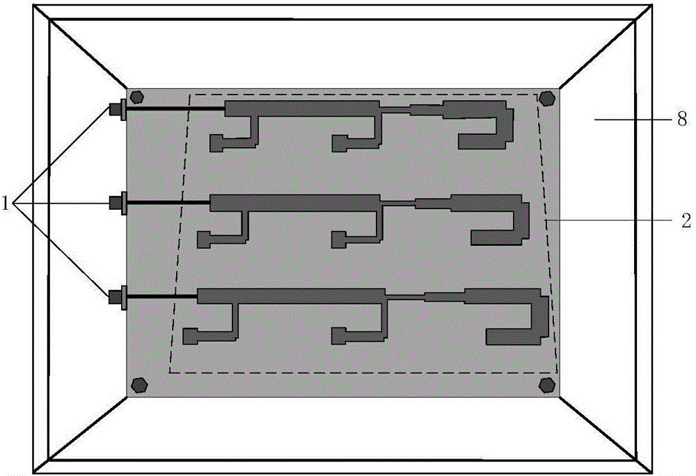
[0021] In the prior art, the design of the horn antenna is more complicated by the design of the loaded dielectric lens structure, which cannot effectively reduce the volume of the horn antenna structurally. Therefore, the present invention proposes a microstrip array-based feeding Miniaturized frequency-swept horn antenna. see figure 1 , a dielectric substrate is installed at the bottom of the rectangular horn 8, the dielectric substrate is divided into a lower dielectric substrate 31 and an upper dielectric substrate 32, the middle of the lower dielectric substrate 31 and the upper dielectric substrate 32 is a radiation floor 4, wherein the lower dielectric substrate 31 and the radiation floor 4 have the same length and width, the lower surface of the lower dielectric substrate 31 is etched with the feed network 2, and one side of the lower dielectric substrate 31 is equipped with a coaxial feed connector 1 for connecting to an external power supply. The upper dielectric su...

Embodiment 2

[0025] The overall composition and specific structure of the miniaturized frequency-swept horn antenna based on microstrip array feeding are the same as in Embodiment 1, see figure 1 , the patch array of the present invention is n groups of sub-arrays of different sizes arranged in parallel, the square radiation patch in each component array is placed parallel to the H plane direction of the rectangular horn 8, and the n component arrays are along the E plane of the rectangular horn 8 The directions are arranged from large to small or from small to large, and n is an odd number greater than 1, which can be 3, 5, 7..., and the specific value depends on the size of the bottom port of the horn antenna in the project. In this example, n is 5, that is to say, there are 5 component arrays to form the overall patch array. In this example, the sub-arrays are arranged in parallel along the E-plane direction of the rectangular horn 8 from small to large, and work in 12GHz, 11GHz, 10GHz,...

Embodiment 3

[0027] The overall composition and specific structure of the miniaturized frequency-swept horn antenna based on microstrip array feeding are the same as those in Embodiment 1-2. In the present invention, n-component arrays of different sizes correspond to square radiation patch arrays at different operating frequencies, see figure 1, the sub-arrays work at different frequencies in a one-to-one correspondence, and each sub-array works at a fixed frequency. The effect of the horn wall is used to make the pattern of the left and right sub-arrays deviate from the main direction. The degree of deviation of the pattern is the same as that of the sub-array The distance to the horn wall on that side is inversely proportional, with the pattern of the centrally located sub-array facing the main direction. In this example, the main direction is the direction facing the horn radiation port, the sub-array located on the left side relative to the center position, the pattern is biased to the...


PUM


Abstract

The invention discloses a small frequency scanning horn antenna based on microstrip array feed, so as to solve the problem that the size of a high-gain horn antenna in the prior art is over large. An upper dielectric substrate is embedded at the bottom port of the horn antenna; a radiant floor is located between the upper dielectric substrate and a lower dielectric substrate; a patch array is etched on the upper surface of the upper dielectric substrate; a feed network is etched on the lower surface of the lower dielectric substrate and is connected with a coaxial feed connector arranged on the side surface; and a microstrip array is formed on the whole. The patch array is formed by sub arrays with different sizes corresponding to different working frequencies. Through using the microstrip array to replace a rectangular waveguide to feed the horn structure, on the premise of ensuring the same gain, the size of the horn antenna can be effectively reduced, the scanning effects of a radiation pattern at different frequencies are realized at the same time, the view point of the antenna is expanded, functions of miniaturization, multi-frequency beam scanning and the like are effectively realized, and the small frequency scanning horn antenna based on microstrip array feed of the invention is applicable to the field such as wireless communication.

Description

technical field [0001] The invention belongs to the technical field of microwave antennas, and relates to a miniaturized frequency-swept horn antenna, in particular to a miniaturized frequency-swept horn antenna based on microstrip array feeding, which is used in fields such as wireless communication and radar. technical background [0002] As a high-quality reflector feed structure and the radiation unit of array antennas, horn antennas have been widely used in satellites, microwave relay communications, phased arrays, and antenna measurements. With the increasing integration of microwave antenna systems, the miniaturization design of horn antennas becomes more and more important. Generally, in order to realize a small horn antenna, it is necessary to reduce the area of ​​the horn terminal aperture and the length of the horn, but this will make it difficult to effectively calibrate the phase distribution of the horn antenna radiation terminal, and reduce the gain of the hor...

Claims


Application Information

Patent Timeline
Patent Type & Authority Applications(China)
IPC IPC(8): H01Q13/02H01Q1/38H01Q1/48H01Q1/50
CPCH01Q1/38H01Q1/48H01Q1/50H01Q13/02
Inventor 杨锐屈亚蓉高东兴陈永朝王青雷振亚
Owner XIDIAN UNIV
Why Eureka
Try Eureka