


Quick Research
Generate reliable direction feasibility study reports for your R&D in just a few steps.

Technical Q&A
Discover and master advanced knowledge NOW. Basics, ideas, possibilities, all at once.

Find Solutions
As an expert in R&D theories, this can generate solutions to your technical problems instantly.

Evaluate Feasibility
Analyze your overall solution with one click, know your potential R&D risks in advance.

Monitor Landscape
Get weekly tech updates, stay abreast of the latest tech innovations and key insights.
Sintered bearing, fluid dynamic bearing device and motor comprising same, and sintered bearing manufacturing method
A technology of sintered bearings and sintered bodies, which is applied in the direction of bearings, shafts, bearings, bearing components, etc., can solve the problems of sintered bearing damage, durability reduction, and inability to obtain the rotation accuracy of shaft parts, etc., and achieve the goal of improving bearing rigidity and pressure Effect
- Summary
- Abstract
- Description
- Claims
- Application Information
AI Technical Summary
Problems solved by technology
Method used
Image

Examples
Embodiment 1
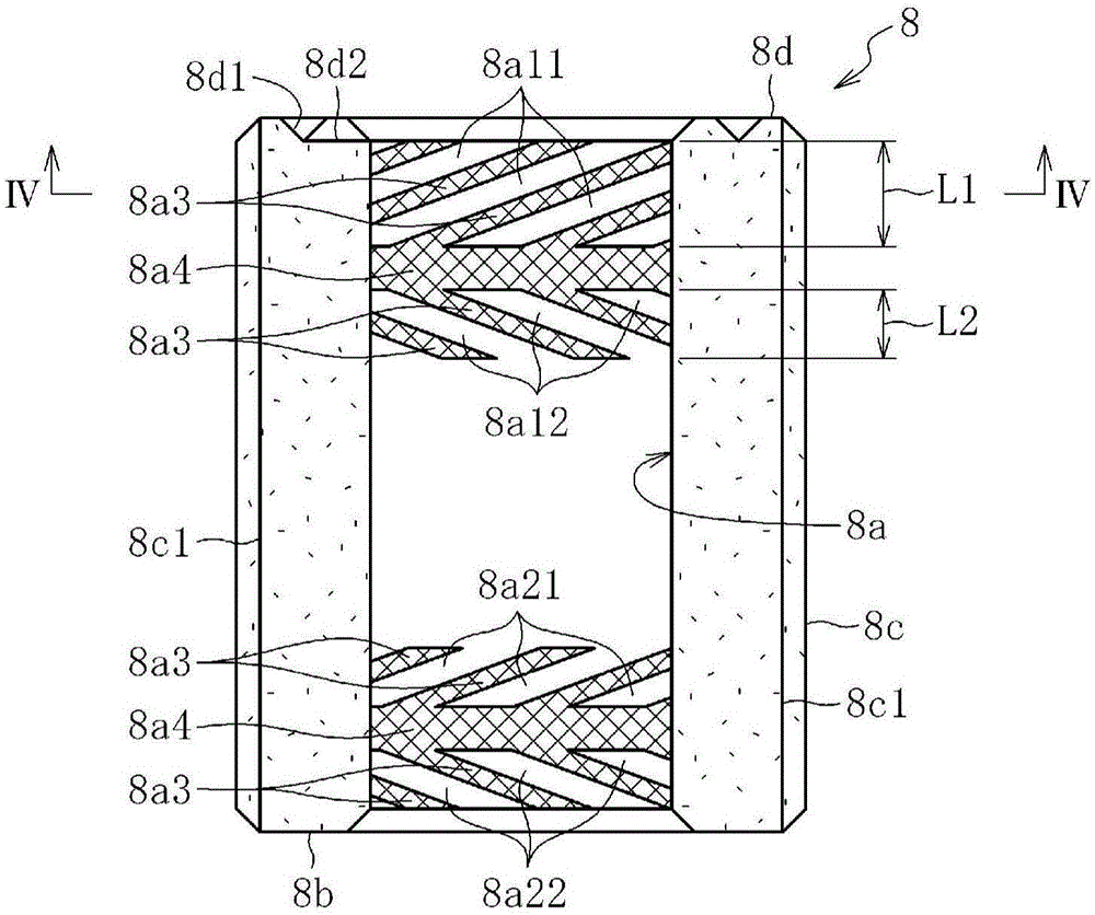
[0071] In order to confirm the effect of the present invention, an implementation product and a comparison product were produced. In the implementation product, the image 3 In the sintered bearings such as the dynamic pressure grooves 8a11 shown, six axial grooves are formed on the outer peripheral surface at equal intervals in the circumferential direction, and in the comparative product, three axial grooves are formed on the outer peripheral surface at equal intervals in the circumferential direction . In these implementation products and comparative products, variations in the groove depths of the dynamic pressure grooves on the same circumference were measured. Specifically, the predetermined axial positions (for example, image 3 According to the roundness waveform of the inner peripheral surface of the IV-IV line), the difference in the radial position of the groove bottom of each dynamic pressure groove relative to the axial center of the sintered bearing is calculate...
Embodiment 2
[0073] In addition, in the comparative product described above, variation in the groove depth of the dynamic pressure grooves was measured when the groove depths of the axial grooves were varied. The result is as Figure 13 As shown, the deeper the groove depth of the axial groove, the greater the deviation of the groove depth of the dynamic pressure groove, especially when the groove depth of the axial groove exceeds 20% of the radial wall thickness of the sintered bearing, the dynamic pressure groove The deviation of the groove depth increases sharply. From this, it can be seen that the groove depth of the axial groove is preferably 20% or less of the radial thickness of the sintered bearing.
PUM
 Abstract
Description
Claims
Application Information
 - R&D Engineer
- R&D Manager
- IP Professional
- Industry Leading Data Capabilities
- Powerful AI technology
- Patent DNA Extraction
Browse by: Latest US Patents, China's latest patents, Technical Efficacy Thesaurus, Application Domain, Technology Topic, Popular Technical Reports.
© 2024 PatSnap. All rights reserved.Legal|Privacy policy|Modern Slavery Act Transparency Statement|Sitemap|About US| Contact US: help@patsnap.com