Metal shell forming process, integrated shell forming process, shell and electronic device

A molding process and shell molding technology, which is applied in the direction of electrical equipment shells/cabinets/drawers, electrical components, casings/cabinets/drawer parts, etc., can solve problems such as poor precision and inability to obtain product shapes, and achieve The effect of short processing time, low cost and precise shape

Inactive Publication Date: 2016-11-16
GUANGDONG OPPO MOBILE TELECOMM CORP LTD
View PDF8 Cites 11 Cited by
  • Summary
  • Abstract
  • Description
  • Claims
  • Application Information

AI Technical Summary

Problems solved by technology

However, in general, the metal shells used for mobile intelligent electronic devices such as smartphones, tablet computers, learning machines, and game consoles are thin and tend to spring back after stamping, so precise product shapes cannot be obtained
Therefore, compared with CNC machining, the accuracy of the existing stamping process is poor

Method used


Image

  • Metal shell forming process, integrated shell forming process, shell and electronic device
  • Metal shell forming process, integrated shell forming process, shell and electronic device
  • Metal shell forming process, integrated shell forming process, shell and electronic device

Examples


Embodiment 1

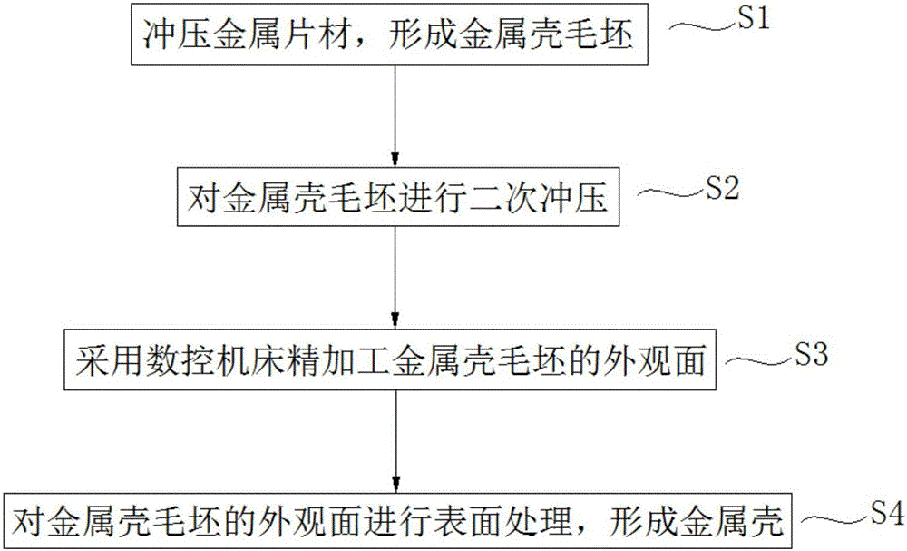
[0038] refer to Figure 1 to Figure 4 , in this embodiment, a metal shell molding process is provided. The metal shell molding process includes the following steps:

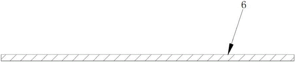
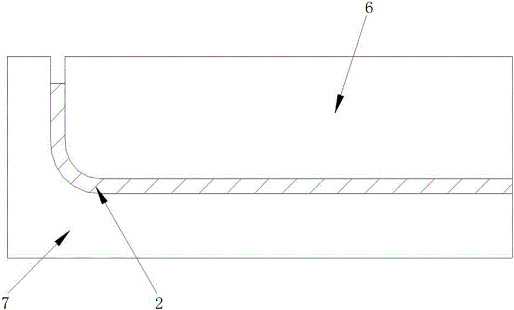
[0039] S1, punch metal sheet 1, form metal shell blank 2 (combine figure 2 and image 3 , image 3 Punch 6 and die 7 used for stamping sheet metal 1 are shown in );

[0040] S2, carrying out secondary stamping to metal shell blank 2, to carry out shaping to metal shell blank 2 (combining Figure 4 ,exist Figure 4 , the downward arrow indicates the direction of stamping);

[0041] S3. Finishing the appearance surface of the metal shell blank 2 with a numerical control machine tool;

[0042] S4. Surface treatment is performed on the appearance surface of the metal shell blank 2 to form a metal shell.

[0043] Thus, after the secondary stamping, the metal shell blank 2 can be shaped, and the springback of the metal shell blank 2 after the first stamping can be compensated, so that an accurate product shape...

Embodiment 2

[0048] refer to Figure 5 to Figure 11 , in this embodiment, an integrated shell molding process is provided, and the integrated shell molding process includes the following steps:

[0049] Step 1, stamping metal sheet 1, forms metal shell blank 2 (combining Image 6 and Figure 7 , Figure 7 Punch 6 and die 7 used for stamping sheet metal 1 are shown in );

[0050] Step 2, carrying out secondary punching to the metal shell blank 2, to shape the metal shell blank 2 (combining Figure 8 ,exist Figure 8 , the downward arrow indicates the direction of stamping);

[0051] Step 3, side punch forming side hole 3 on metal shell blank 2 (combined with Figure 9 );

[0052] Step 4. Mold the plastic part 4 on the metal shell blank 2 by in-mold injection molding to form an integrated shell, wherein the mold for in-mold injection molding is provided with bumps (such as lateral sliders), during the injection molding process , the bump is inserted into the side hole 3 and seals the...

Embodiment 3

[0065] This embodiment provides an integrated shell, which is made by the integral shell molding process described in Embodiment 2, and its partial structure can be referred to Figure 11 structure shown. The one-piece shell has precise shape, short processing time, and low cost of the one-piece shell. Preferably, the one-piece housing of this embodiment is one-piece battery cover.


PUM

PropertyMeasurementUnit
thicknessaaaaaaaaaa

Abstract

The invention relates to the field of electronic device parts and machining methods thereof, in particular to a metal shell forming process, an integrated shell forming process, a shell and an electronic device. The metal shell forming process includes the steps that a metal sheet is stamped to form a metal shell blank; the metal shell blank is stamped for the second time; the appearance surface of the metal shell blank is subjected to finish machining; and the appearance surface of the metal shell blank is subjected to surface treatment. The integrated shell forming process includes the steps that a metal sheet is stamped to form a metal shell blank; the metal shell blank is stamped for the second time; the metal shell blank is subjected to lateral punching to form a side hole; plastic parts are formed on the metal shell blank; the appearance surface and the side hole of the metal shell blank are subjected to finish machining; and the appearance surface of the metal shell blank is subjected to surface treatment. By means of the metal shell forming process and the integrated shell forming process, precise product appearance can be obtained, and the machining time is short. The integrated shell is formed through the integrated shell forming process. The electronic device comprises the integrated shell, and the electronic device and the integrated shell have precise appearance and are short in machining time.

Description

technical field [0001] The invention relates to the field of electronic device parts and processing methods thereof, in particular to a metal shell forming process, an integral shell forming process, an integral shell and an electronic device. Background technique [0002] On mobile intelligent electronic devices such as smartphones, tablet computers, learning machines, and game consoles, all-metal shells are more and more widely used. At present, the most widely used ones are processed by CNC machine tools (CNC) to obtain product shapes and obtain better shapes. The quality of the appearance surface, and obtaining the shape of the product through CNC often consumes a lot of CNC time, resulting in high costs. [0003] Now there has been a stamping process to form a metal shell. It first cuts the metal blank into a rough blank with a set size, then stamps the rough blank and deburrs it to obtain a semi-finished electronic device cover. However, generally speaking, the metal ...

Claims


Application Information

Patent Timeline
Patent Type & Authority Applications(China)
IPC IPC(8): B23P15/00B21D35/00H05K5/02
CPCB21D35/002B21D35/003B23P15/00B29C2045/14868H05K5/0217
Inventor 许海平成蛟
Owner GUANGDONG OPPO MOBILE TELECOMM CORP LTD
Why Eureka
Try Eureka