A fully automatic welding method for photovoltaic panels and an automatic photovoltaic panel welding machine for realizing the method

An automatic welding machine and a fully automatic welding technology, applied in the field of solar energy applications, can solve problems such as unguaranteed quality, low work efficiency, and increased costs, and achieve the effects of reducing unstable factors, reducing labor costs, and improving production efficiency

Active Publication Date: 2016-08-17
东莞市开胜电子有限公司
View PDF10 Cites 0 Cited by
  • Summary
  • Abstract
  • Description
  • Claims
  • Application Information

AI Technical Summary

Problems solved by technology

[0002] Ribbon is the carrier used to connect cells in solar cells. It plays a conductive role. The main component is copper. The welding ribbon is cut to the required length, and the cutting is performed by a welding ribbon cutting machine. The welding ribbon cutting machine currently used, after the welding ribbon is cut, it must be manually controlled to a certain amount to stop cutting, and the welding ribbon will be cut. The ribbons are stored separately according to the quantity, and then the ribbons are manually welded to the photovoltaic board. In this way, there are disadvantages of low work efficiency, and there are human factors, and its quality cannot be guaranteed, resulting in an increase in cost.

Method used


Image

  • A fully automatic welding method for photovoltaic panels and an automatic photovoltaic panel welding machine for realizing the method
  • A fully automatic welding method for photovoltaic panels and an automatic photovoltaic panel welding machine for realizing the method
  • A fully automatic welding method for photovoltaic panels and an automatic photovoltaic panel welding machine for realizing the method

Examples


Embodiment Construction

[0032] The present invention will be described in further detail below in conjunction with the accompanying drawings.

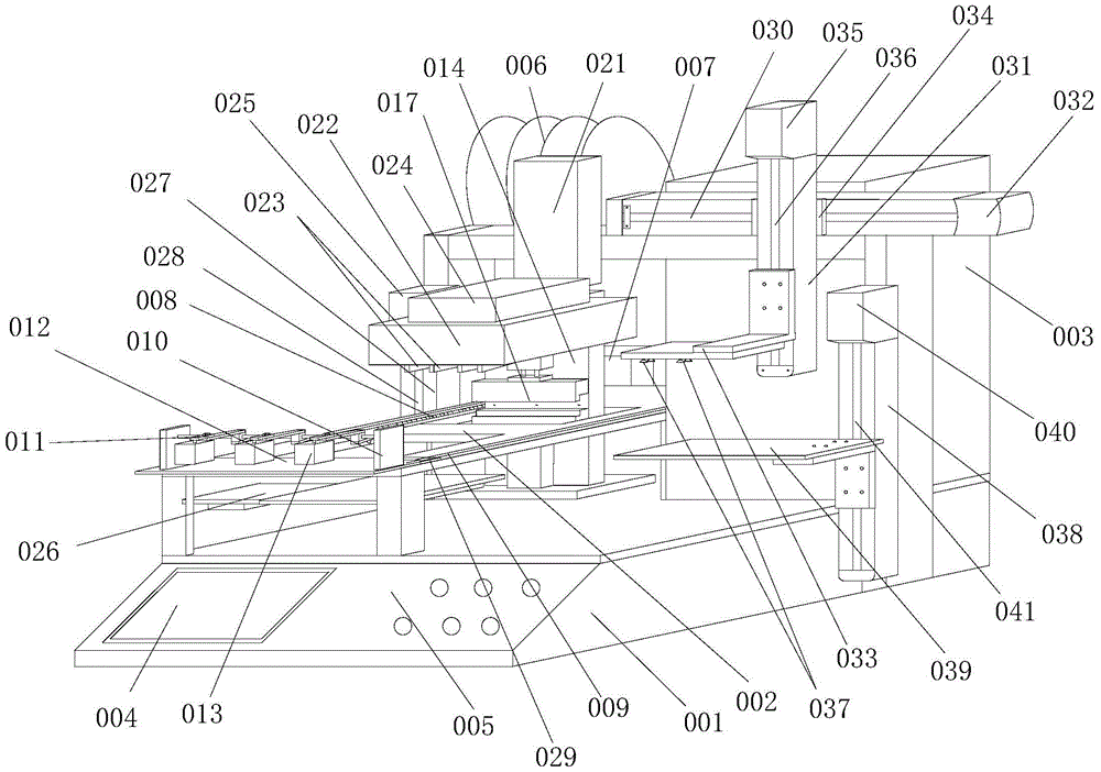
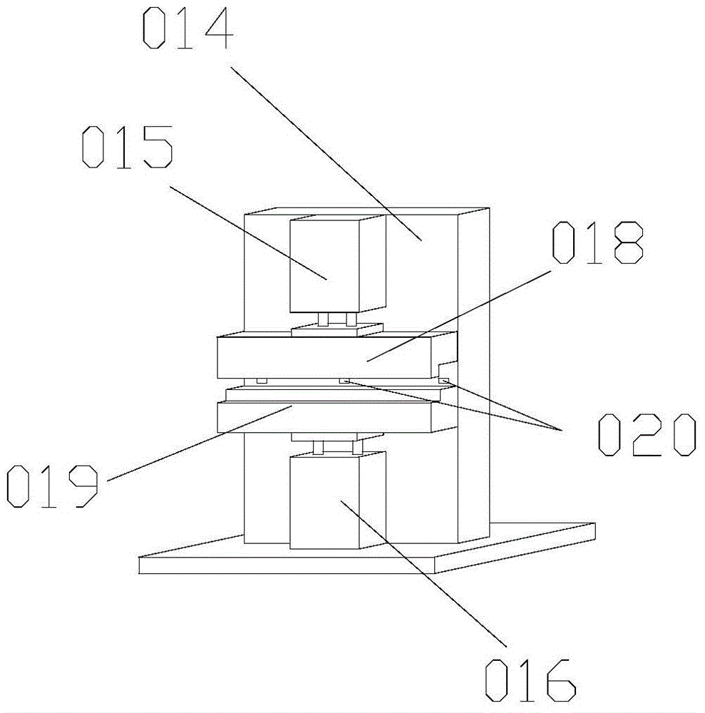
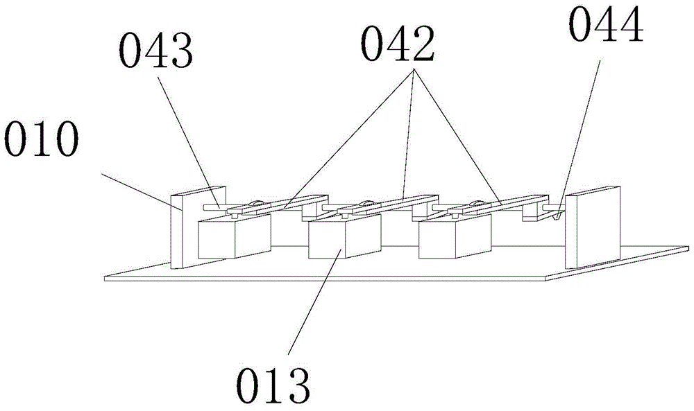
[0033] Figure 1 to Figure 5A photovoltaic panel automatic welding machine according to the present invention is schematically shown.

[0034] According to one aspect of the present invention, there is provided an automatic welding machine for photovoltaic panels, a fully automatic welding method for photovoltaic panels, comprising the following steps:

[0035] (1) First stack multiple photovoltaic panels on the feeder, and install the ribbon on the ribbon conveyor system;

[0036] (2) The ribbon conveying mechanism starts and clamps the ribbon, transports the ribbon to the top of the feeder, and straightens the ribbon;

[0037] (3) The feeder rises so that the photovoltaic panel placed on the top of the feeder is in contact with the ribbon;

[0038] (4) The welding mechanism is lowered so that the bead set on the welding mechanism can be in contact with t...


PUM


Abstract

The invention discloses a full-automatic welding method of a photovoltaic panel. The method comprises the following steps of stacking a plurality of photovoltaic panels on a feeder, and mounting a solder strip on a solder strip conveying system; starting a solder strip conveying mechanism, clamping the solder strip, conveying the solder strip to a position above the feeder and tightening the solder strip; lifting the feeder, and enabling the photovoltaic panel on the top of the feeder to contact with the solder strip; dropping a welding mechanism, enabling a depression bar on the welding mechanism to contact with the solder strip, pressing the solder strip by the depression bar under the effect of gravity, clinging the solder strip to the photovoltaic panel, releasing the solder strip by the solder strip conveying mechanism, continuing dropping the welding mechanism to cover the photovoltaic panel, enabling a heating tube on the welding mechanism to work, transferring heat to a working position by a blowing mechanism, and welding the solder strip on the photovoltaic panel; after completion, cutting off the solder strip by a cutoff mechanism, resetting the welding mechanism, and automatically unloading by an unloading system. The invention provides an automatic photovoltaic panel welding machine capable of realizing the method.

Description

technical field [0001] The invention relates to the field of solar energy applications, in particular to a fully automatic welding method for photovoltaic panels and an automatic photovoltaic panel welding machine for realizing the method. Background technique [0002] Ribbon is the carrier used to connect cells in solar cells. It plays a conductive role. The main component is copper. The welding ribbon is cut to the required length, and the cutting is performed by a welding ribbon cutting machine. The welding ribbon cutting machine currently used, after the welding ribbon is cut, it must be manually controlled to a certain amount to stop cutting, and the welding ribbon will be cut. The ribbons are stored separately according to the quantity, and then the ribbons are manually welded to the photovoltaic panel. In this way, there are disadvantages of low work efficiency, and there are human factors, and the quality cannot be guaranteed, resulting in an increase in cost. Cont...

Claims


Application Information

Patent Timeline
Patent Type & Authority Patents(China)
IPC IPC(8): B23K31/02B23K37/00B23K37/04
CPCB23K1/012B23K3/0607B23K3/08B23K3/087
Inventor 夏德湘
Owner 东莞市开胜电子有限公司
Why Eureka
Try Eureka