Crossed-material-conveyance die cutting machine

A material mold and cutting machine technology, which is applied in lamination devices, metal processing, lamination and other directions, can solve the problems of increased production costs, increased working hours, waste of materials, etc., and achieves the effect of high production efficiency and material saving

Active Publication Date: 2016-11-16
LINGSHENGCHENG TECH JIANGSU CO LTD
View PDF5 Cites 6 Cited by
  • Summary
  • Abstract
  • Description
  • Claims
  • Application Information

AI Technical Summary

Problems solved by technology

Existing die-cutting machines can only feed in one direction, and can only die-cut after the materials are laminated. For products with large spacing, there will be more waste between the products after die-cutting, which is a waste of materials. Moreover, the cleaning of waste materials leads to an increase in man-hours, resulting in an increase in production costs.

Method used


Image

  • Crossed-material-conveyance die cutting machine

Examples


Embodiment Construction

[0016] The content of the present invention will be further described in detail below in conjunction with the accompanying drawings.

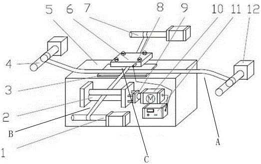
[0017] Such as figure 1 As shown, a cross-feeding die-cutting machine includes a base 5, a first feeding mechanism B, a second feeding mechanism A, and a die-cutting mechanism C. The first feeding mechanism B and the second feeding mechanism A are installed on both sides of the base 5 . The die-cutting mechanism C is installed in the middle of the base 5 . The feeding directions of the first feeding mechanism B and the second feeding mechanism A are perpendicular to each other. The feeding directions of the first feeding mechanism B and the second feeding mechanism A intersect each other below the die-cutting mechanism C. Further preferably, the first feeding mechanism B includes a first feeding roller 1, a first receiving roller 7, and a first carrier film. Both ends of the first carrier film are connected to the first feeding roller 1 and...


PUM


Abstract

The invention discloses a crossed-material-conveyance die cutting machine comprising a base, a first material conveyance mechanism, a second material conveyance mechanism and a die cutting mechanism. The first material conveyance mechanism and the second material conveyance mechanism are installed on the two sides of the base. The die cutting mechanism is installed in the middle of the base. The material conveyance direction of the first material conveyance mechanism and the material conveyance direction of the second material conveyance mechanism are mutually perpendicular and converge below the die cutting mechanism. The crossed-material-conveyance die cutting machine can conduct die cutting and compounding of materials at the same time and is high in production efficiency and suitable for volume production. Meanwhile, the first material conveyance mechanism and the second material conveyance mechanism achieve asynchronous die cutting, so that the product interval requirement is met, and materials are saved.

Description

technical field [0001] The invention relates to the technical field of die-cutting, in particular to a cross-feeding die-cutting machine. Background technique [0002] At present, in the die-cutting industry, die-cutting machines are divided into flat die-cutting machines, spiral die-cutting machines, and optical calibration die-cutting machines, which are mainly used for some corresponding non-metallic materials, self-adhesive, instant noodles, double-sided adhesive, Die-cutting, indentation, hot stamping, lamination, and automatic waste discharge of insulating films. Die-cutting machines use steel knives, metal molds, and steel wires to apply a certain pressure through the embossing plate to tie the printed matter or cardboard into a certain shape. Shape is an important equipment for printing and packaging processing. Existing die-cutting machines can only feed in one direction, and can only die-cut after the materials are laminated. For products with large spacing, there...

Claims


Application Information

Patent Timeline
Patent Type & Authority Applications(China)
IPC IPC(8): B26F1/44B26D5/22B26D7/06B32B37/00
CPCB26D5/22B26D7/0625B26F1/44B32B37/00
Inventor 龙绍勤
Owner LINGSHENGCHENG TECH JIANGSU CO LTD
Why Eureka
Try Eureka