Composite movable mold frame for cast-in-situ box beam and construction method of composite movable mold frame

A mobile formwork and composite technology, used in bridges, bridge construction, erection/assembly of bridges, etc., can solve the problems of poor adaptability, repeated removal of formwork and formwork supports, and low construction efficiency.

Active Publication Date: 2016-11-16
德州市公路工程总公司
View PDF6 Cites 17 Cited by
  • Summary
  • Abstract
  • Description
  • Claims
  • Application Information

AI Technical Summary

Problems solved by technology

[0004] The purpose of the present invention is to propose a cast-in-place box girder composite mobile formwork and its construction in view of the shortcomings of the traditional cast-in-place box girder support formwork, such as poor adaptability, low construction efficiency, and repeated r

Method used


Image

  • Composite movable mold frame for cast-in-situ box beam and construction method of composite movable mold frame
  • Composite movable mold frame for cast-in-situ box beam and construction method of composite movable mold frame
  • Composite movable mold frame for cast-in-situ box beam and construction method of composite movable mold frame

Examples


Embodiment Construction

[0035] The present invention will be further described in detail below with reference to the accompanying drawings and examples. The following examples are explanations of the present invention and are not limited to the following examples.

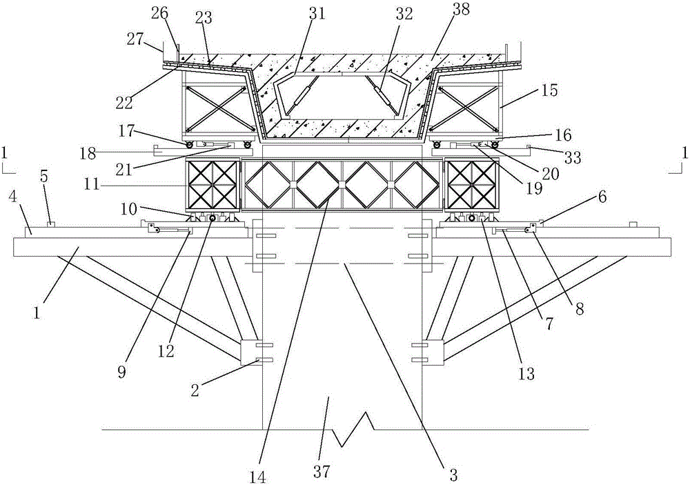
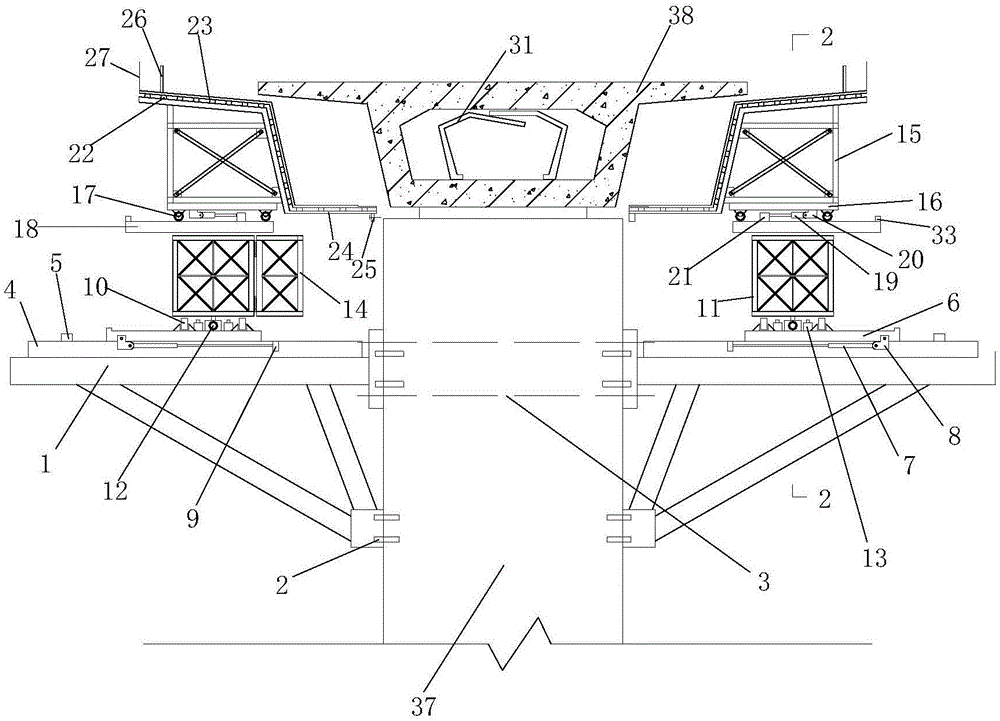
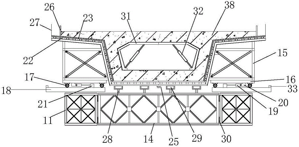
[0036] figure 1 It is a cross-sectional view of the construction state of the cast-in-place box girder based on the composite mobile formwork. like figure 1 The composite mobile formwork shown mainly includes: corbel support bracket 1, traversing track 4, pulley block platform 6, longitudinal Bailey beam 11, transverse Bailey beam 14, outer mold support 15, traversing platform 16, Traverse jack A7, longitudinal jack 35, traverse jack B19, baffle mold 26 and guardrail 27.

[0037] The traversing track 4 is set on the corbel support bracket 1, and the limit block A5 is set on the outside of the traversing track 4; the pulley block platform 6 is placed on the traversing track 4, and the longitudinal pulley A10 is set on the pulley block pl...


PUM


Abstract

The invention relates to a composite movable mold frame for a cast-in-situ box beam. The composite movable mold frame mainly comprises a corbel supporting bracket, a horizontal movement railway, pulley block platforms, longitudinal bailey beams, horizontal bailey beams, external mold brackets, horizontal movement platforms, horizontal movement jacks A, a longitudinal movement jack and horizontal movement jacks B, wherein the horizontal movement jacks A are arranged on the side surface of the pulley block platforms and the side surface of the horizontal movement railway, one ends of the horizontal movement jacks A are fixed on the pulley block platforms, and the other ends of the horizontal movement jacks A are fixed on the horizontal movement railway; the longitudinal movement jack is arranged under the longitudinal bailey beams in a longitudinal direction; a base of the longitudinal movement jack is fixed on the pulley block platforms, and the other end of the base is fixed on a longitudinal movement guide rail beam through a connecting fitting E; and the external mold brackets adopt a structure that two sides of the external mold bracket are in symmetry and separation, and bottom mold plates on two sides are fixed together through bolts. The structure of the composite movable mold frame disclosed by the invention is convenient to disassemble and assemble and high in construction efficiency, repeated disassembling of supports and mold frame structures is not needed, automated hole penetration of the movable mold frame and a main beam can be realized, the serial construction of the cast-in-situ box beam is realized, and good economic and technical benefits are achieved.

Description

technical field [0001] The invention relates to a composite mobile formwork for a cast-in-place box girder, which belongs to the field of building construction engineering, and in particular to a construction method for a cast-in-place box girder based on a composite mobile formwork. Background technique [0002] Prestressed concrete girder bridges occupy a dominant position in my country's small and medium-span bridges. In addition to the commonly used full pavement method of pouring hole by hole and whole hole prefabricated erection, the construction method also uses a large number of mobile formwork to pour hole by hole, which effectively promotes bridge construction. The mechanization process of construction. [0003] The traditional cast-in-place box girder supporting formwork has poor adaptability, low construction efficiency, and the formwork and formwork brackets need to be removed repeatedly. In order to adapt to the different structural systems and structural chara...

Claims


Application Information

Patent Timeline
IPC IPC(8): E01D21/00
CPCE01D21/00
Inventor 沈红燕韩京利赵丹裴德社王文勇
Owner 德州市公路工程总公司
Why Eureka
Try Eureka