Concrete vibration device

A vibrating device and concrete technology, which is applied in construction, building structure, and construction material processing, etc., can solve problems such as endangering personal safety, short circuit of power supply, and falling off of electrical box connections, and achieve high compaction quality and work efficiency The effect of increasing and reducing manpower

Inactive Publication Date: 2016-11-16
朱万银
View PDF7 Cites 5 Cited by
  • Summary
  • Abstract
  • Description
  • Claims
  • Application Information

AI Technical Summary

Problems solved by technology

On-site power system, cables dragging the floor, damaged during dragging, and disconnected from the connection with the electric box, seriously causing short circuit of power supply and electric shock, endangering personal safety

Method used


Image

  • Concrete vibration device
  • Concrete vibration device
  • Concrete vibration device

Examples


Embodiment Construction

[0020] The principles and features of the present invention are described below in conjunction with the accompanying drawings, and the examples given are only used to explain the present invention, and are not intended to limit the scope of the present invention.

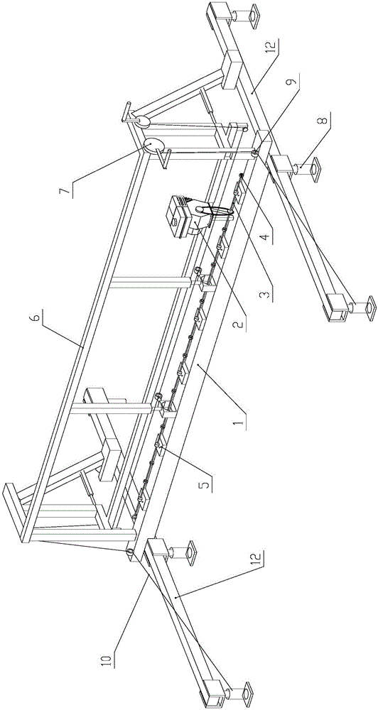
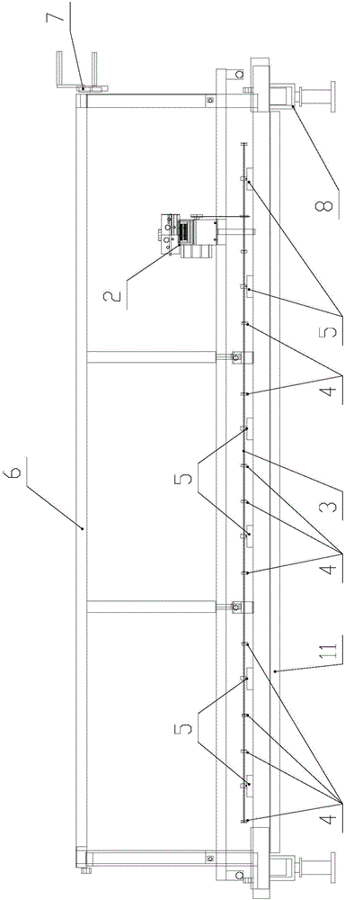
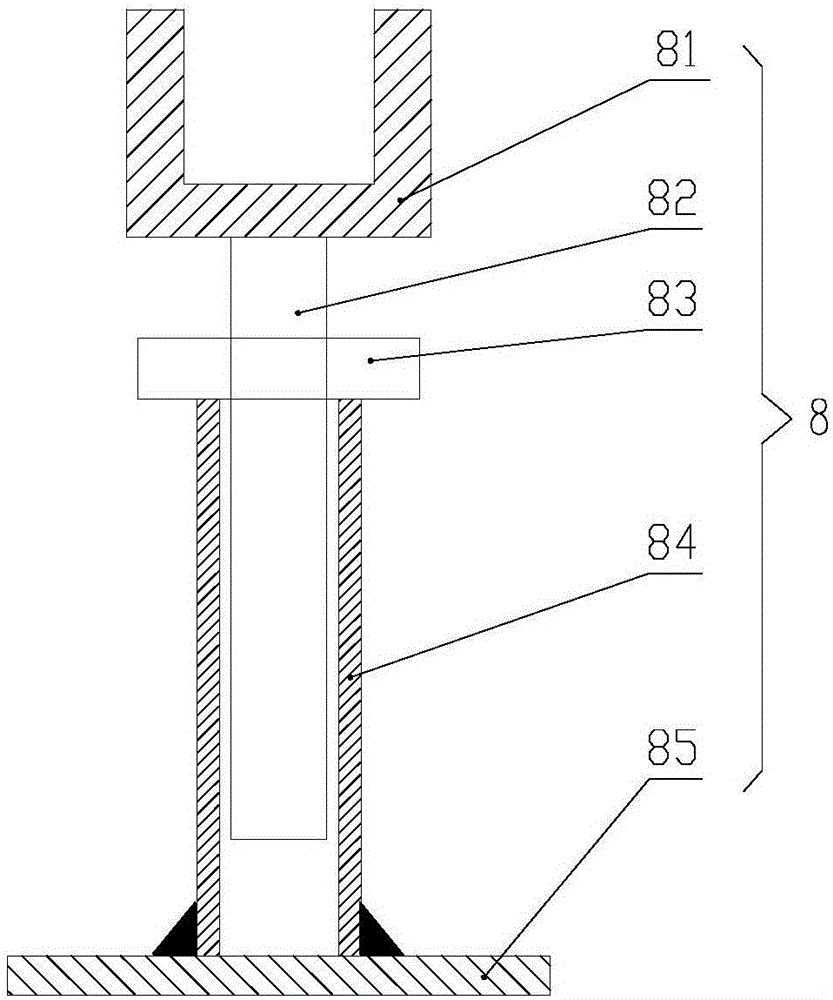
[0021] Such as Figure 1 to Figure 4 as shown, figure 1 It is a schematic diagram of the overall three-dimensional structure of a specific embodiment of a concrete vibrating device provided by the present invention; figure 2 for figure 1 Front view of the specific embodiment shown; image 3 It is a structural schematic diagram of the height adjustment device; Figure 4 It is a partially enlarged schematic diagram of the eccentric wheel being installed on the transmission shaft.

[0022] A kind of concrete vibrating device provided in the present invention comprises a vibrating beam 1, a transmission shaft 3, an eccentric wheel 4 and a power unit 2; The shaft 3 is installed on the vibrating beam 1 along the len...


PUM


Abstract

The invention relates to a concrete vibration device. The concrete vibration device comprises a vibration beam, a transmission shaft, eccentric wheels and a power device; the vibration beam is horizontally placed on the concrete needing to be vibrated to be flat; the transmission shaft is installed on the vibration beam in the length direction of the vibration beam; the transmission shaft is connected with the vibration beam in a rotation mode; the eccentric wheels are fixedly installed on the transmission shaft; the centers of gravity of the eccentric wheels are not in the rotation center line of the vibration beam; and the power device is installed on the vibration beam and is connected with the transmission shaft in a transmission mode to drive the transmission shaft to rotate. The concrete vibration device is not only high in working efficiency, but also capable of reducing the number of operators, thereby reducing labor cost.

Description

technical field [0001] The invention relates to the field of building construction, in particular to a concrete vibrating device. Background technique [0002] Concrete pouring is a necessary process in building construction. In traditional concrete pouring, after the concrete is put into the warehouse and spread out, the vibrating rod is used to vibrate and extract the pulp with the plum blossom point insertion method, and then a large amount of manual use is used to level it with corresponding scrapers. surface, then press the surface with a washboard trowel, and finally use an iron trowel to make a smooth surface. This traditional concrete pouring mode requires a large amount of labor to complete more tedious work, which not only has low work efficiency, but also has high labor costs, which can be described as a waste of money. Not only that, but the site was messy, with tools scattered around. On-site power system, cable mopping the floor, damage during towing, and fal...

Claims


Application Information

Patent Timeline
Patent Type & Authority Applications(China)
IPC IPC(8): E04G21/06
CPCE04G21/066
Inventor 吴志钢朱万银程增龙
Owner 朱万银
Why Eureka
Try Eureka