A pneumatic integrated device with hydraulic damping

An integrated device, hydraulic damping technology, applied in the direction of fluid pressure actuation device, etc., can solve the problems of flow change, the difficulty of guaranteeing the cylinder moving speed, etc., to achieve the effect of reduced speed, simple structure and accurate positioning

Active Publication Date: 2018-07-27
ZHEJIANG KINGLAND & PIPELINE TECH
View PDF7 Cites 0 Cited by
  • Summary
  • Abstract
  • Description
  • Claims
  • Application Information

AI Technical Summary

Problems solved by technology

In a compressed air system, small-scale fluctuations in pressure are unavoidable, which will directly lead to changes in flow, especially during conversion and working stages, and the moving speed of the cylinder will be difficult to guarantee

Method used


Image

  • A pneumatic integrated device with hydraulic damping
  • A pneumatic integrated device with hydraulic damping
  • A pneumatic integrated device with hydraulic damping

Examples


Embodiment 1

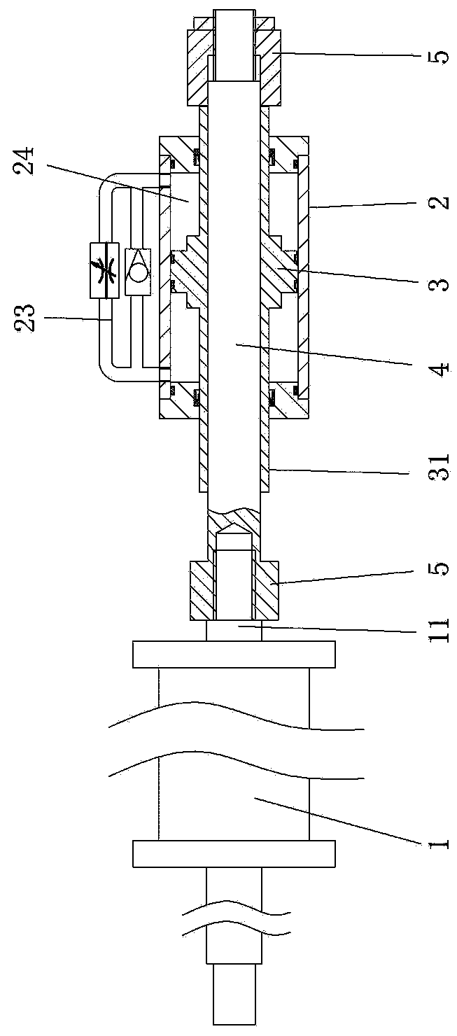
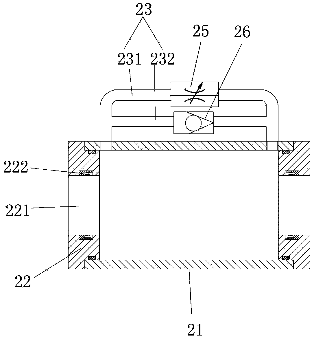
[0021] Embodiment 1: as figure 1 and figure 2 As shown, a pneumatic integrated device with hydraulic damping includes a cylinder, including a cylinder 1. The cylinder 1 is a double-extended push rod cylinder. The end of the push rod 11 of the cylinder 1 is connected with a damping mechanism. The damping mechanism includes a damping mechanism. cylinder 2, damping piston 3 and movable rod 4, the damping piston 3 is arranged in the damping cylinder 2 and moves relative to the damping cylinder 2, and the damping piston 3 divides the inner chamber of the damping cylinder 2 into two A damping chamber 24, the damping chamber 24 communicates through the circulating oil passage 23. The circulating oil circuit 23 includes a two-way oil circuit 231 and a one-way oil circuit 232 , the two-way oil circuit 231 is provided with a throttle valve 25 , and the one-way oil circuit 232 is provided with a one-way valve 26 . Both the two-way oil passage 231 and the one-way oil passage 232 commun...

Embodiment 2

[0024] Embodiment 2: as Figure 4 As shown, the difference from Embodiment 1 is that a fixed magnetic block 27 is provided on the outside of the end cover 22, and a fixed magnetic block 27 is provided on the limit block 5 located on the same side of the end cover 22. The moving magnet block 28 of repulsive force.


PUM


Abstract

The invention relates to the technical field of pneumatic elements, in particular to a pneumatic integration device with hydraulic damping. The device comprises an air cylinder and a damping mechanism; the damping mechanism comprises a damping cylinder, a damping piston and a movable rod; the damping piston is arranged in the damping cylinder and can move relative to the damping cylinder, an inner cavity of the damping cylinder is divided into two damping cavities through the damping piston, and the damping cavities are communicated through a circular oil path; a limiting rod extending to the outer side of the damping cylinder is arranged in the damping piston in the moving direction of the damping piston, and the limiting rod moves together with the damping piston; the movable rod is fixedly connected to a push rod, and penetrates the limiting rod to be arranged on the damping piston in a sleeving manner, through pushing of the pushing rod, the movable rod moves relative to the damping piston, and a limiting block for pushing the limiting rod to move is arranged at the end of the movable rod. The device is simple in structure, wide in use range, accurate in positioning, capable of controlling the forward speed of the air cylinder and capable of achieving various speed requirements, and the speed is relatively stable.

Description

technical field [0001] The invention relates to the technical field of pneumatic components, in particular to a pneumatic integrated device with hydraulic damping. Background technique [0002] Due to its advantages in power structure, cylinders are widely used in linear motion places under small loads. One of the methods needs to use different speeds in different designated areas. For example, in the process of advancing, the starting point 0 to the working starting point A requires the fastest moving speed; the working starting point A to the working end point B requires an appropriate moving speed; the working end point B needs to move as fast as possible to return to the starting point 0. At present, it is usually achieved by changing the air supply flow rate of the cylinder, that is, when the need is fast, increase the air supply; that is, when the need is slow, reduce the air supply; the change of the air supply is through the air The replacement of the valve is real...

Claims


Application Information

Patent Timeline
Patent Type & Authority Patents(China)
IPC IPC(8): F15B15/22
CPCF15B15/228
Inventor 杨伟芳鲍小荣朱文闯王超莫建新曹月良
Owner ZHEJIANG KINGLAND & PIPELINE TECH
Why Eureka
Try Eureka