
Floating ball type self-balance dewatering device and dewatering circulation area calculating method thereof

A flow area, self-balancing technology, applied in the direction of steam traps, mechanical equipment, etc., can solve the problems of unable to maintain the water level in the heater, easy to malfunction, and many mechanical moving parts, etc., to achieve a simple structure and a wide range of applications , The effect of fewer mechanical moving parts

Inactive Publication Date: 2016-11-16
CHINA ENERGY ENG GRP GUANGDONG ELECTRIC POWER DESIGN INST CO LTD
View PDF9 Cites 3 Cited by
  • Summary
  • Abstract
  • Description
  • Claims
  • Application Information

AI Technical Summary

Problems solved by technology

[0011] One of the purposes of the present invention is to solve the problems that existing balanced drain valves or drain systems have many mechanical moving parts, are prone to failure or malfunction, steam leakage or failure to maintain the water level in the heater, etc., to provide a Floating ball self-balancing hydrophobic device

Method used


Image

  • Floating ball type self-balance dewatering device and dewatering circulation area calculating method thereof
  • Floating ball type self-balance dewatering device and dewatering circulation area calculating method thereof
  • Floating ball type self-balance dewatering device and dewatering circulation area calculating method thereof

Examples


specific Embodiment 1

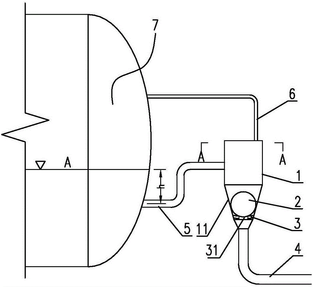
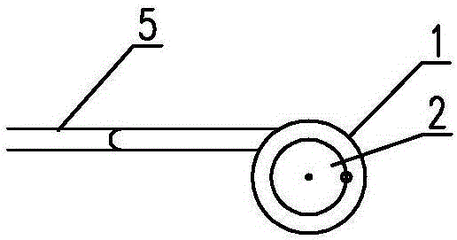
[0046] refer to figure 1 with figure 2The floating ball type self-balancing drainage device shown includes a housing 1, a floating ball 2, a drainage pipe 4, a water inlet pipe structure 5 and an air balance pipe 6, and the housing 1 is arranged higher than the heat exchanger 7 in the drainage system At the normal water level position A, a water outlet 11 is provided at the bottom of the housing 1, and a floating ball 2 is arranged at the water outlet 11 to open or close the water outlet 11. The air space position on the upper part of the heater 7 is to form an aerodynamic balance structure to balance the air pressure between the housing 1 and the heat exchanger 7; The structure 5 communicates with the water outlet of the heat exchanger 7 to transport the hydrophobic water of the heat exchanger 7 to the shell 1; the drain end of the shell 1 is set on the bottom surface of the shell 1 and is used for draining the water by communicating with the drain pipe 4 ; Form the hydrau...

specific Embodiment 2

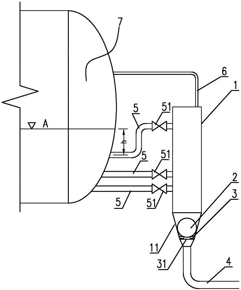
[0069] The technical features of this implementation are: image 3 As shown, the water inlet pipeline structure 5 is composed of a plurality of water pipes, one end of the water inlet pipeline 5 is connected to the heat exchanger 7, and the other end is connected to the connecting pipe of the housing 1, and each connecting pipe connects the drain of the heat exchanger 7 transported into housing 1. There are several guide grooves distributed around the inner wall of the water outlet 11, and the guide grooves are used to guide the water above the floating ball 2 to the bottom of the floating ball 2 to form the floating force of the floating ball. A plurality of water inlet pipes 5 with different elevations can be arranged between the shell 1 and the heat exchanger 77, and a switching valve 51 is arranged on the water inlet pipe 5 to realize automatic control of various water levels. All the other are the same as the above embodiment.


PUM


Abstract

The invention relates to a floating ball type self-balance dewatering device and a dewatering circulation area calculating method thereof. The floating ball type self-balance dewatering device comprises a shell, a floating ball, a drain pipe, a water inlet pipe structure and a gas balance pipe; the shell is arranged in a normal water level position higher than a heat exchanger in a dewatering system; a water outlet is formed in the bottom end of the shell; the floating ball is arranged in the water outlet; the top of the shell is communicated with an upper gas space position of the heat exchanger through the gas balance pipe; the shell is provided with a water inlet end and a drain end; the water inlet end of the shell is communicated with a water outlet end of the heat exchanger through the water inlet pipe structure to convey water of the heat exchanger into the shell; and the drain end of the shell is arranged on the bottom surface of the shell, and is communicated with the drain pipe. The floating ball type self-balance dewatering device has such characteristics and beneficial effects as simple structure, few mechanical moving parts, rigidity, durability, prevention of the steam leakage, prevention of the heat loss, prevention of the environmental pollution, low working environment requirement and wide application range.

Description

technical field [0001] The invention relates to a floating ball type self-balancing hydrophobic device and a method for calculating the hydrophobic flow area thereof. The utility model relates to a drain device suitable for maintaining the water level of condensed water so as to maintain the balance of heating steam in and out, and belongs to the technical field of steam heating equipment in electric power systems. Background technique [0002] The drain system is an important system in the steam heating process. A well-performed drain system can ensure that only condensed water is discharged to prevent high-grade steam leakage loss. The drain system can also be used to maintain the condensed water level to maintain the balance of heating steam in and out. [0003] At present, there are mainly mechanical, thermodynamic, thermostatic, gas-liquid two-phase balance systems, power delivery systems and water level control valves for hydrophobic balance. details as follows: [0...

Claims


Application Information

Patent Timeline
Patent Type & Authority Applications(China)
IPC IPC(8): F16T1/20F16T1/38
CPCF16T1/20F16T1/383
Inventor 霍沛强樊晓茹
Owner CHINA ENERGY ENG GRP GUANGDONG ELECTRIC POWER DESIGN INST CO LTD
Learn More