A pipeline monitoring system
A monitoring system and pipeline technology, applied in the electronic field, can solve the problems of pipeline leakage, low positioning accuracy, poor real-time monitoring, etc., and achieve the effect of monitoring leakage and improving positioning accuracy.
- Summary
- Abstract
- Description
- Claims
- Application Information
AI Technical Summary
Problems solved by technology
Method used
Image
Examples
Embodiment 1
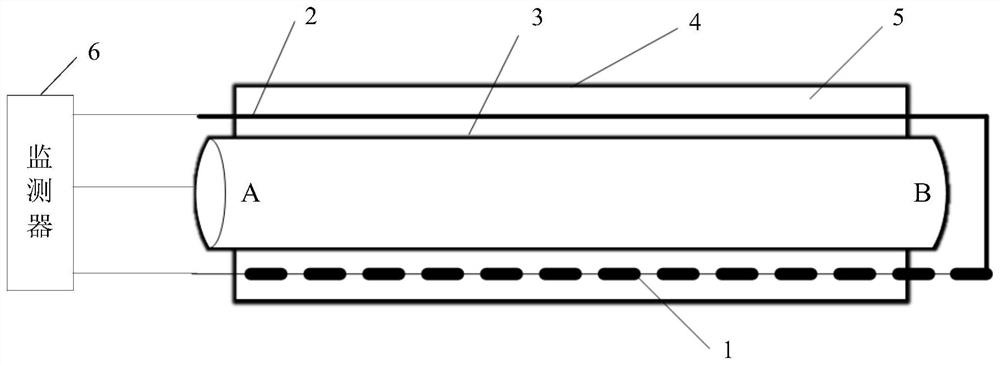
[0033] This embodiment provides a pipeline monitoring system, such as figure 1 shown. The pipeline to be monitored is a metal pipeline, and a pipeline insulation layer 5 and a pipeline shell 4 are arranged on the outer layer of the pipeline steel pipe 3 . Between the two ends A and B of the pipeline steel pipe 3 is the monitored pipeline part. Pipe insulation layer 5 adopts insulating material, and foam can be used. In the insulation layer 5 of the pipeline to be monitored, the sensing line 1 and the feedback line 2 are pre-embedded along the axial direction of the pipeline, and one end of the sensing line 1 and the feedback line 2 is connected outside the B end of the pipeline steel pipe 3 .
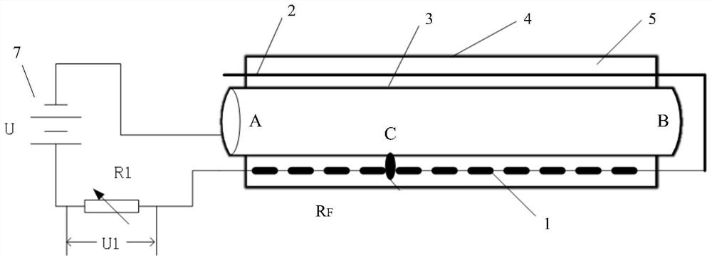
[0034] The pipeline monitoring system includes a sensing line 1 , a feedback line 2 and a monitor 6 . The sensing line 1 is wrapped with an insulating layer, and the insulating layer is distributed with through holes along the length direction to expose the sensing line 1. When the m...
Embodiment 2
[0041] This embodiment provides a pipeline network monitoring system, the structural diagram of the pipeline network monitoring system is as follows image 3 As shown, it includes a plurality of pipeline monitoring systems 31 as described in Embodiment 1, a plurality of positioning devices 32 and a remote monitoring terminal 33 .
[0042] The pipeline network monitoring system includes N pipelines 30, and each pipeline is provided with N pipeline monitoring systems 31 for monitoring the leakage status of each pipeline. At the N pipeline monitoring systems, N positioning devices 32 are correspondingly provided for determining the position of each pipeline monitoring system.
[0043] The remote monitoring terminal 33 is connected to N pipeline monitoring systems 31 and N positioning devices 32 respectively, and is used to receive the leakage status of each pipeline and the location of the corresponding pipeline monitoring system. As a specific implementation, the pipeline leaka...
Embodiment 3
[0046] This embodiment provides a pipeline leak detection method, the flow chart of the method is as follows Figure 4 As shown, it specifically includes the following steps:
[0047] S1: Obtain the first voltage and the second voltage from the leak point on the detection line in the insulation layer of the detected pipeline to the two ends of the pipeline. As a specific implementation, such as Figure 5 As shown, first obtain the first voltage U2 from the leakage point C on the detection line in the insulation layer 5 of the pipeline to be detected, that is, the leakage point C on the sensing line 1, to the A end of the pipeline steel pipe; Figure 6 As shown, the second voltage U3 from the leakage point C on the detection line in the thermal insulation layer 5 of the pipeline to be detected, that is, on the sensing line 1 to the end of the pipeline steel pipe B, is obtained.
[0048] S2: Calibrate the actual length of the detected pipeline according to the first voltage an...
PUM
 Abstract
Description
Claims
Application Information
 - R&D
- Intellectual Property
- Life Sciences
- Materials
- Tech Scout
- Unparalleled Data Quality
- Higher Quality Content
- 60% Fewer Hallucinations
Browse by: Latest US Patents, China's latest patents, Technical Efficacy Thesaurus, Application Domain, Technology Topic, Popular Technical Reports.
© 2025 PatSnap. All rights reserved.Legal|Privacy policy|Modern Slavery Act Transparency Statement|Sitemap|About US| Contact US: help@patsnap.com


