A kind of non-coupling pre-splitting charge device and using method

A charging and pre-splitting technology, applied in blasting and other directions, can solve the problems of time-consuming, labor-intensive, complicated charging process, etc., and achieve the effect of reducing the amount of dust, having a wide range of sources and being convenient to carry.

Active Publication Date: 2017-06-27
ANSTEEL GRP MINING CO LTD
View PDF6 Cites 0 Cited by
  • Summary
  • Abstract
  • Description
  • Claims
  • Application Information

AI Technical Summary

Problems solved by technology

[0005] The purpose of the present invention is to solve the practical engineering construction problems such as complex charging process, time-consuming and labor-intensive, and provide a non-coupling pre-split charging device and its use method

Method used


Image

  • A kind of non-coupling pre-splitting charge device and using method
  • A kind of non-coupling pre-splitting charge device and using method
  • A kind of non-coupling pre-splitting charge device and using method

Examples


Embodiment 1

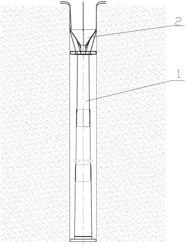
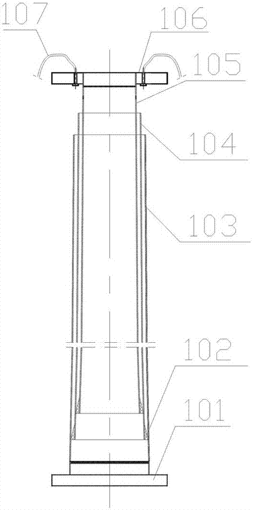
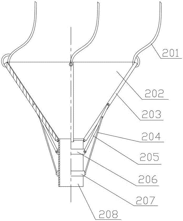
[0030] like figure 1 , 2 , As shown in 3, a non-coupling pre-split charge device is composed of variable-diameter non-coupled pre-split charge cartridge 1 and umbrella-shaped charge device 2.

[0031] Variable-diameter non-coupling pre-split cartridge 1 consists of a bottom cover 101, a bottom tube 103 threaded with the bottom cover 101, and a group of intermediate tubes 104 inserted in this bottom tube 103 in turn, and inserted into this group The top cylinder 105 in the middle cylinder 104 is composed of the central positioning ring 106 threadedly connected with the top cylinder 105 and the manual pull rope 107 arranged on the central positioning ring 106. The outer surface of the bottom of the intermediate cylinder 104 and the top cylinder 105 is All have rubber anti-slip sleeves 102, and the cylinder diameters of the set of intermediate cylinders 104 decrease successively from bottom to top;

[0032] The centering ring 106 should be a group of spare parts with different ...

Embodiment 2

[0042] The depth of the pre-splitting hole in the test is 15 m, the diameter of the pre-splitting hole is 250 mm, and the filling length of the blast hole is 4.5 m. In the device of implementation 1, the taper angle of the truncated conical barrel with variable diameter uncoupled pre-split cartridge is 0.4°, the diameter of the upper end of the top barrel is 93 mm, and the diameter of the lower end of the bottom barrel is 240 mm, including each barrel of the middle barrel The length is 1.64 m, and there are 7 barrels in total; the diameter of the barrel of the umbrella-shaped charge used is 50 mm.

[0043] The steps of the specific method of using the uncoupled pre-split charge device are as follows:

[0044] (1) Assemble a top cylinder, a bottom cylinder, and 5 intermediate cylinders into a variable-diameter uncoupled pre-split cartridge, and install the bottom cover on the lower end of the bottom cylinder and tighten it;

[0045] (2) Put the combined cartridges into the hol...

Embodiment 3

[0051] The depth of the pre-splitting hole in the test is 12 m, the diameter of the pre-splitting hole is 220 mm, and the filling length of the blast hole is 3.6 m. In the device of implementation 1, the cone angle of the tapered tube of the variable diameter uncoupled pre-split cartridge is 0.4°, the diameter of the upper end of the top tube is 108 mm, and the diameter of the lower end of the bottom tube is 210 mm, including the diameter of each tube of the middle tube. The length is 1.34 m, and there are 7 cylinders in total; the diameter of the cylinder is 60 mm using the umbrella-shaped charge in the hole.

[0052] The steps of the specific method of using the uncoupled pre-split charge device are as follows:

[0053] (1) Choose one top cylinder, one bottom cylinder, and 5 intermediate cylinders to assemble into a variable-diameter uncoupled pre-split cartridge, install the bottom cover on the lower end of the bottom cylinder and tighten it;

[0054] (2) Put the combined ...


PUM


Abstract

The invention aims to solve the actual engineering construction problems that the explosive charging process is complex, time is consumed and labor is consumed, provides a non-coupling pre-splitting explosive charging device and a using method, and belongs to the technical field of surface blasting engineering. The device is composed of a variable-diameter non-coupling pre-splitting explosive charging barrel and an umbrella-shaped explosive charging device; and the umbrella-shaped explosive charging device is located on the upper portion of the variable-diameter non-coupling pre-splitting explosive charging barrel. According to the device, the length of the explosive charging barrel can be flexibly and fast changed according to the on-site hole depth changing length and the non-coupling coefficient, and the requirement that the explosive charging non-coupling coefficient is sequentially decreased from bottom to top in the whole explosive charging device is met; the device can enter blast holes of different diameters and is automatically opened according to the size of the blast holes, and explosives can be conveniently injected into an explosive charging vehicle; and blasting crushing regions and the blasting tight bottom can be reduced, and side walls are effectively protected.

Description

technical field [0001] The invention belongs to the technical field of open-pit blasting engineering, and in particular relates to an uncoupled pre-splitting charge device and a use method. Background technique [0002] It is widely used in side blasting in slope excavation of large-scale hydropower projects, rock and soil blasting in urban construction or foundation pit excavation blasting, side blasting in large open-pit mining and production blasting in some non-metallic mines. The common requirements are: reduce the damage of explosives to the side slope, protect the integrity of the side slope, and then reduce the maintenance cost of the side slope; reduce the blasting seismic wave intensity, reduce the vibration damage of the blasting to the side slope and excessive crushing around the blast hole. [0003] The uncoupling charge technology is often used in practical engineering. The radial uncoupling is realized by reducing the diameter of the grain column, and the axia...

Claims


Application Information

Patent Timeline
Patent Type & Authority Patents(China)
IPC IPC(8): F42D1/08F42D3/04
CPCF42D1/08F42D3/04
Inventor 潘鹏飞孙厚广徐连生徐冬林栾辉刘鑫徐振洋张大宁
Owner ANSTEEL GRP MINING CO LTD
Why Eureka
Try Eureka