
Composite vibrating wire sensor device for displacement measurement of three directions

A vibrating wire sensor, displacement measurement technology, applied in measurement devices, instruments, using ultrasonic/sonic/infrasonic waves, etc., can solve the problems of large amplitude, long excitation time, large energy consumption, etc. cost saving effect

Active Publication Date: 2016-11-16
CHANGAN UNIV
View PDF5 Cites 5 Cited by
  • Summary
  • Abstract
  • Description
  • Claims
  • Application Information

AI Technical Summary

Problems solved by technology

[0004] Since the displacement measurement of the structure involves displacement in three directions, the vibrating wire sensor can only obtain the displacement along the string direction, and cannot realize the all-round monitoring of the structure; Sweep frequency excitation is to select the appropriate frequency segment according to the natural frequency of the sensor, and apply a 5V frequency sweep pulse train signal to the sensor with gradually increasing frequency. When the frequency of the excitation signal is close to the natural frequency of the steel string, the steel string can Reach the resonance state quickly, the amplitude of the resonance state is the largest, can generate a large induced electromotive force, the frequency signal output by the sensor has a high signal-to-noise ratio and is easy to measure
[0005] However, since the frequency sweep signal is a continuous pulse signal from the lower frequency limit to the upper frequency limit, in order to ensure the excitation effect, the pulse of each frequency must last for several cycles, and the excitation time is too long, resulting in high energy consumption, which limits the sensor In the application of remote unattended measurement system, in order to improve the battery life and save energy consumption, it is necessary to improve the electric excitation method of the vibrating wire sensor

Method used


Image

  • Composite vibrating wire sensor device for displacement measurement of three directions
  • Composite vibrating wire sensor device for displacement measurement of three directions
  • Composite vibrating wire sensor device for displacement measurement of three directions

Examples


Embodiment Construction

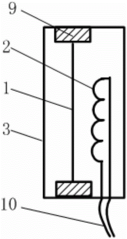
[0036] Such as figure 1 As shown, the vibrating wire sensor belongs to the frequency sensor, which can be equivalent to a vibrating steel string whose frequency at both ends changes with the tension of the steel wire, including the vibrating wire 1, the coil 2, the sensor housing 3 and the lead wire 10, and the vibrating wire 1 is fixed on On the positioning support 9 at both ends of the sensor housing 3, the coil 2 is arranged in the middle of the vibrating wire 1, the circuit generates an excitation signal, the driving coil generates magnetic force to drive the vibrating wire 1 to vibrate, and detects the vibration of the vibrating wire 1.

[0037] Under electric excitation, the vibrating wire 1 vibrates according to its natural frequency, and changing the tension F of the vibrating wire 1 can obtain different vibration frequencies F, that is, the relationship between tension and resonance frequency is a single-valued function. When the length of the vibrating wire under ten...


PUM


Abstract

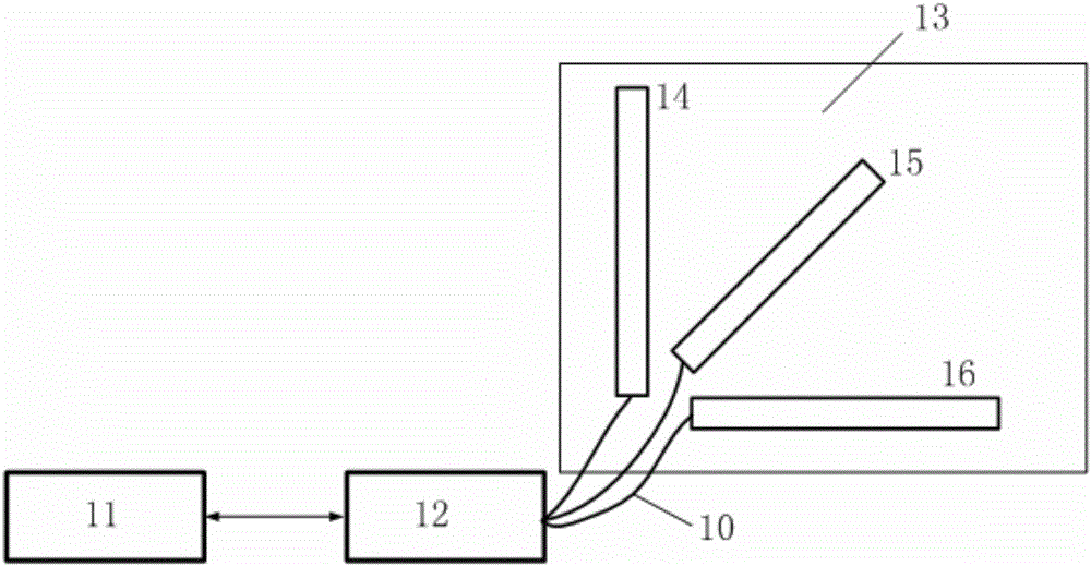
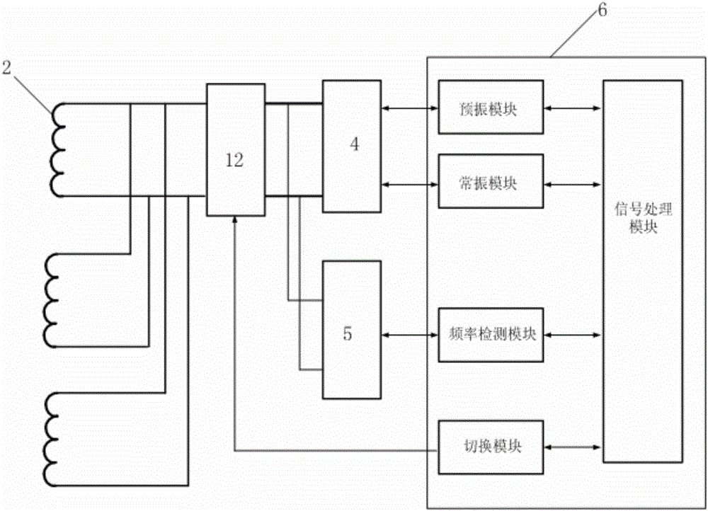
The invention discloses a composite vibrating wire sensor device for displacement measurement of three directions. The device comprises a detection unit, a switcher as well as an X-axis vibrating wire sensor head, a Y-axis vibrating wire sensor head and a Z-axis vibrating wire sensor head arranged inside a target to be measured, wherein the X-axis vibrating wire sensor head, the Y-axis vibrating wire sensor head and the Z-axis vibrating wire sensor head are in three directions perpendicular to one another, and the detection unit is used for excitation, vibration pick-up and displacement measurement of the vibrating wire sensor heads; and the detection unit controls the switcher to sequentially communicate with the three sensor heads according to a time sequence, thereby acquiring the displacement values of the target to be measured in three directions. The invention further provides a vibrating wire sensor excitation detection mode with low power consumption, which greatly reduces the energy consumption while realizing all-directional displacement measurement in the structure and meets the requirement of a sensor for long-time work under the unmanned and battery power supply condition.

Description

technical field [0001] The invention belongs to the field of structure measurement, and in particular relates to displacement or deformation measurement of large structures in the construction field. Background technique [0002] In the daily maintenance of large structures, it is very important to measure the deformation or displacement of its key components. The stress magnitude and distribution changes of the above-mentioned stressed components most directly reflect the health of the structure. Therefore, the stress status monitoring of these components And the safety analysis and evaluation based on this is of great significance. [0003] The vibrating wire sensor is one of the most advanced sensors in the application of force measurement at present. Its sensitive element is a metal wire string, which is connected and fixed with the force-bearing part of the sensor. Various physical quantities are measured by the tension relationship. This sensor outputs frequency signa...

Claims


Application Information

Patent Timeline
Patent Type & Authority Applications(China)
IPC IPC(8): G01B17/00G01B17/04
CPCG01B17/00G01B17/04
Inventor 陈建勋刘钦罗彦斌黄沛高文武
Owner CHANGAN UNIV
Learn More