
TBM excavation section anchor rod anti-drawing detection experiment device and using method

A test device and anti-pull technology, applied in the direction of measuring devices, mechanical devices, instruments, etc., can solve the problems of not being able to use the TBM equipment platform, increase the difficulty of bolt detection, and not carry out in time, so as to reduce the time-consuming detection test , Easy to promote and use, simple structure

Inactive Publication Date: 2016-11-16
SINOHYRDO ENG BUREAU 3 CO LTD
View PDF5 Cites 1 Cited by
  • Summary
  • Abstract
  • Description
  • Claims
  • Application Information

AI Technical Summary

Problems solved by technology

[0002] The fast excavation speed of TBM is one of the characteristics superior to the traditional manual drilling and blasting method, which can reach about 30 meters per day. Due to the rapid excavation of TBM, if the pull-out detection of anchor rods is not carried out in time, the TBM equipment platform will not be able to be used for subsequent inspections. will encounter great difficulties
The distance between the TBM device and the surrounding rock of the formed cave wall is only about 20cm. In order to ensure the safe passage of the TBM equipment, about 10cm of the bolt is actually reserved, and the effective working length of the bolt resistance equipment is about 40cm; and the bolt that comes with the TBM The bolt installed on the drilling rig has a certain inclination, which increases the difficulty of bolt detection

Method used


Image

  • TBM excavation section anchor rod anti-drawing detection experiment device and using method
  • TBM excavation section anchor rod anti-drawing detection experiment device and using method

Examples


Embodiment Construction

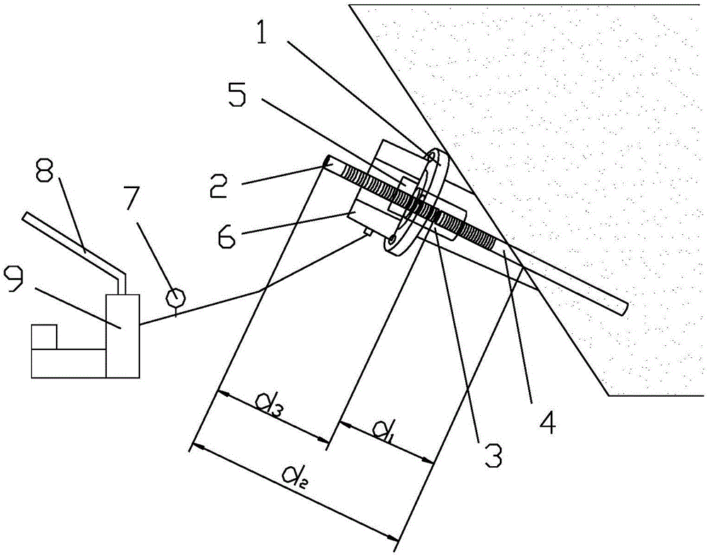
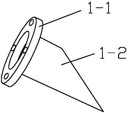
[0031] Such as figure 1 with figure 2 As shown, the present invention includes a bolt extension mechanism, a pressure member 1 and a pulling force loading mechanism. The connecting piece 3 of the rod 2 and the anchor rod 4, the pressure bearing 1 includes a pressure bearing plate 1-1 and a support pipe 1-2 through which the connecting piece 3 can pass, and the pressure bearing plate 1-1 is provided with The through hole for the connector 3 to pass through, the pressure bearing plate 1-1 is fixedly connected with the support pipe 1-2, the cross section of the support pipe 1-2 is an inclined surface, and the inclination angle of the inclined surface is related to the inclination The inclination angle of the rock face matches.

[0032] Such as figure 1 As shown, in this embodiment, the pulling force loading mechanism includes a hollow jack 6, a hydraulic pump 9 connected to the hollow jack 6, and an anchor joint 5 for connecting the anchor extension rod 2, on the hydraulic pu...


PUM


Abstract

The invention discloses a TBM excavation section anchor rod anti-drawing detection experiment device which comprises an anchor rod extending mechanism, a pressure-bearing part and a drawing force loading mechanism. The anchor rod extending mechanism comprises an anchor rod extension rod and a connecting part used for connecting the anchor rod extension rod with an anchor rod, the pressure-bearing part comprises a pressure-bearing plate and a supporting tube, the pressure-bearing plate is provided with a through hole allowing the connecting part to pass through, the pressure-bearing part is fixedly connected with the supporting tube, and the cross section of the supporting tube is an inclined plane. The invention further discloses a using method of the TBM excavation section anchor rod anti-drawing detection experiment device. The TBM excavation section anchor rod anti-drawing detection experiment device is simple in structure and reasonable in design, the length of the exposed anchor rod is extended to the effective length of the anti-drawing force of the anchor rod through a threaded sleeve and the extension rod, the problem that an inclination angle exists between the anchor rod and the inclined rockface is solved, the application range is wide, the engineering cost is effectively reduced, the consumed time of the detection experiment is shortened, using and operating are convenient, the practicability is high, the using effect is good, and application and popularization are convenient.

Description

technical field [0001] The invention belongs to the technical field of anchor rods, and in particular relates to a pullout detection test device and a use method of an anchor rod in a TBM excavation section. Background technique [0002] The fast excavation speed of TBM is one of the characteristics superior to the traditional manual drilling and blasting method, which can reach about 30 meters per day. Due to the rapid excavation of TBM, if the pull-out detection of anchor rods is not carried out in time, the TBM equipment platform will not be able to be used for subsequent inspections. will encounter great difficulties. The distance between the TBM device and the surrounding rock of the formed cave wall is only about 20cm. In order to ensure the safe passage of the TBM equipment, about 10cm of the bolt is actually reserved, and the effective working length of the bolt resistance equipment is about 40cm; and the bolt that comes with the TBM The bolt installed on the drilli...

Claims


Application Information

Patent Timeline
Patent Type & Authority Applications(China)
IPC IPC(8): G01N19/04
CPCG01N19/04
Inventor 姜建波杨红宁万春义
Owner SINOHYRDO ENG BUREAU 3 CO LTD
Learn More