A Calculation Method for Subsurface Current Field Distribution in Zoned and Stratified Soil

A technology of partition layering and calculation method, applied in the field of high-voltage electricity, can solve problems such as the difficulty of finite element calculation, and achieve the effect of avoiding inaccurate calculation and simple calculation method.

Active Publication Date: 2018-08-21
TSINGHUA UNIV +1
View PDF4 Cites 0 Cited by
  • Summary
  • Abstract
  • Description
  • Claims
  • Application Information

AI Technical Summary

Problems solved by technology

Although the finite element can analyze the electromagnetic field distribution under the combination of various media, it is mainly used to analyze the problem in the limited area. In this example, the potential distribution area is very large, and the current goes to infinity. It is an open domain problem, and the finite element calculation is used There are difficulties

Method used


Image

  • A Calculation Method for Subsurface Current Field Distribution in Zoned and Stratified Soil
  • A Calculation Method for Subsurface Current Field Distribution in Zoned and Stratified Soil
  • A Calculation Method for Subsurface Current Field Distribution in Zoned and Stratified Soil

Examples


Embodiment 1

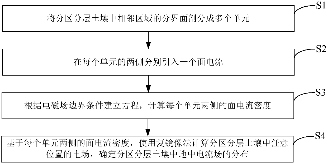
[0040] Such as figure 1 As shown, the present invention provides a calculation method for the distribution of the ground current field in the divided and layered soil, which is used to calculate the ground current generated in the ground by the grounding device of electrical engineering (including substations, converter stations, towers, grounding poles, etc.) A wide range of voltage distribution; which includes:

[0041] S1. Divide the interface of adjacent areas in the partitioned and layered soil into multiple units, and the units meet the unique boundary condition. The only boundary condition is that the soil resistivity of any side of the area on both sides of the unit is unique.

[0042] S2. Introduce a surface current on both sides of each unit, and the surface currents on both sides correspond to the regions on both sides of the unit;

[0043] S3. Establish an equation according to the electromagnetic field boundary conditions, and calculate the surface current densit...

Embodiment 2

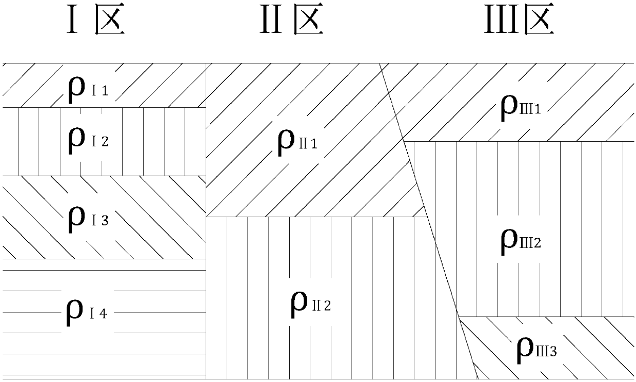
[0064] Algorithm of the present invention and the calculation result of COMSOL software are contrasted, and the soil condition of each partition and conductor location are as follows: Figure 6 shown; Figure 6 Among them, the soil in area Ⅰ is divided into two layers in the horizontal direction. The soil resistivity of the first layer is 10Ω·m, the thickness is 300m, and the resistivity of the second layer is 100Ω·m. The resistivity of the second layer is 50Ω·m and the thickness is 100m. The resistivity of the second layer is 20Ω·m and the thickness is 400m. The resistivity of the third layer is 500Ω·m. The resistivity is 100Ω·m, the thickness is 200m, and the resistivity of the second layer of soil is 1000Ω·m. The position of the conductor and the position of the observation line are the same as in Example 1. The calculation result of the inventive method and the calculation result of COMSOL are as Figure 7 shown.

[0065] From Figure 7 It can be seen that when the so...


PUM


Abstract

The invention discloses a calculating method for electric current field distribution of soil grounds in partitions and layers. The method comprises following steps: dividing interfaces of adjacent regions of soil in partitions and layers into multiple units; guiding one surface current to two sides of each unit; calculating surface current density on two sides of each unit by calculating equations according to electromagnetic field boundary conditions; using a complex image method to calculate electric fields at any position of soil in partitions and layers based on surface current density on two sides of each unit so that distribution of soil grounds in partitions and layers can be determined. The calculating method for electric current field distribution of soil grounds in partitions and layers has following beneficial effects: by guiding surface current to interfaces and combining with a complex image method, complex soil in partitions are equally taken as simple single-layer soil; the calculating method is easy by taking very complex soil structures; by using boundary conditions of electromagnetic fields, equations are created so that accuracy of calculating results is ensured; and the method is capable of analyzing electric field distribution at infinite distance.

Description

technical field [0001] The invention relates to the technical field of high-voltage electricity, in particular to a calculation method for subsurface current field distribution in subdivided and layered soil. Background technique [0002] The grounding device is an important protection facility during work, faults and lightning strikes. It is used to release working currents (such as DC grounding electrodes operating with the ground as a loop), fault currents (such as power frequency short circuits) and lightning currents to the ground. At this time, a large current flows into or out of the ground from the grounding device, and this current forms a potential distribution in the soil, threatening the safety of nearby people and equipment. [0003] At present, the soil model that can be considered when calculating the potential distribution formed by the ground current in the ground of the grounding device is mainly a single layer of resistivity or a simple block distribution ...

Claims


Application Information

Patent Timeline
Patent Type & Authority Patents(China)
IPC IPC(8): G06F17/50
CPCG16Z99/00
Inventor 张波何金良廖永力曹方圆李锐海孟晓波庄池杰曾嵘
Owner TSINGHUA UNIV
Why Eureka
Try Eureka