Adjustable box-type substation

A box-type substation and box technology, which is applied to enclosed substations, substations, substation/distribution device casings, etc., can solve problems such as high sealing performance requirements, poor practicability, and complex structure.

Active Publication Date: 2016-11-16
山东恒东实业集团有限公司
View PDF8 Cites 18 Cited by
  • Summary
  • Abstract
  • Description
  • Claims
  • Application Information

AI Technical Summary

Problems solved by technology

However, such a heat dissipation method needs to continuously add water to the roof box, and the sealing performance requirements of the box and the water supply pipeline are high, and the load on the side wall of the box is

Method used


Image

  • Adjustable box-type substation
  • Adjustable box-type substation
  • Adjustable box-type substation

Examples


Embodiment 1

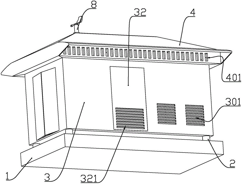
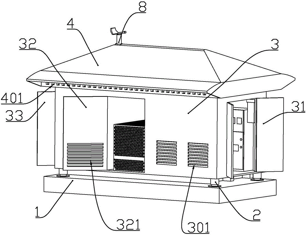
[0073] according to Figure 1 to Figure 12 As shown, this embodiment is a liftable box-type substation, which includes a base 1 made of reinforced concrete, and a box body 3 in the shape of a rectangular parallelepiped disposed above the base.

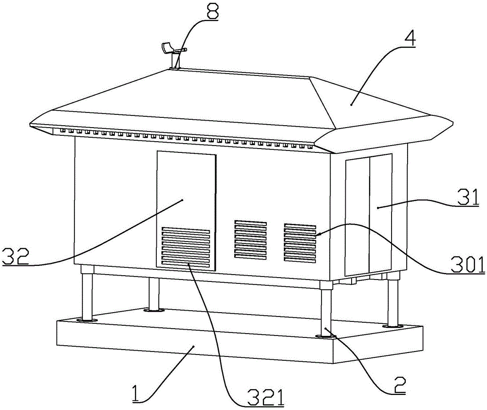
[0074] A longitudinally arranged electric push rod 2 is installed in the box near the four vertices, and the output rod of the electric push rod passes downward through the bottom plate at the lower end of the box and is fixedly connected to the base.

[0075] A liquid level sensor (not shown) is installed on the lower end of the output rod or on the base; the liquid level sensor and each electric push rod are respectively electrically connected with a control box, and the control box is installed inside the box.

[0076]When the liquid level sensor detects accumulated water, the control box controls the electric push rod to extend to lift the box body, and the lifting height of the box body is proportional to the water level detected ...

Embodiment 2

[0089] according to Figure 1 to Figure 12 As shown, this embodiment is a liftable box-type substation, which includes a base 1 made of reinforced concrete, and a box body 3 in the shape of a rectangular parallelepiped disposed above the base.

[0090] A longitudinally arranged electric push rod 2 is installed in the box near the four vertices, and the output rod of the electric push rod passes downward through the bottom plate at the lower end of the box and is fixedly connected to the base.

[0091] A liquid level sensor (not shown) is installed on the lower end of the output rod or on the base; the liquid level sensor and each electric push rod are respectively electrically connected with a control box, and the control box is installed inside the box.

[0092] When the liquid level sensor detects accumulated water, the control box controls the electric push rod to extend to lift the box body, and the lifting height of the box body is proportional to the water level detected...


PUM


Abstract

The invention discloses an adjustable box-type substation, which comprises a base and a box body arranged at the upper part of the base, wherein the upper part of the box body is connected with a head cover; the head cover comprises longitudinal walls and slope walls; the lower parts of the longitudinal walls are fixedly connected with horizontally arranged transverse walls; exhaust outlets are uniformly formed in two groups of longitudinal walls, along the length direction, of the head cover; slide chute sockets are formed in the positions, corresponding to the exhaust outlets, of the transverse walls; wind grid plates are connected to the inside of the slide chute sockets in a sliding manner; grid plate openings which are used in fit with the exhaust outlets are formed in the corresponding wind grid plates; grid plate push rods are arranged on the inner walls of the transverse walls, along the width direction, of the head cover; an output rod of each grid plate push rod is fixedly connected with the end part of the corresponding wind grid plate; and a wind direction sensor is also arranged at the upper end of the head cover. The adjustable box-type substation is compact in structure, reasonable in design, convenient to construct and good in cooling effect.

Description

technical field [0001] The invention belongs to the field of electric equipment, and in particular relates to a structure of a liftable box-type substation. Background technique [0002] The Chinese patent with the document number CN204271514U discloses a waterproof box-type substation, which solves the problem that in the event of natural disasters such as floods and heavy rainstorms, a large amount of water will enter the box-type substation with a relatively high water level, which will cause damage to the large-area box-type substation. The main point of the technical solution is to provide a lifting mechanism so that the power distribution equipment can be lifted and lowered, and a box body is provided with a stretching mechanism, which can also increase the height of the box body when the power distribution equipment is lifted, so that the water will not touch the Power distribution equipment, to protect the power distribution equipment, the box can be stretched to...

Claims


Application Information

Patent Timeline
IPC IPC(8): H02B1/28H02B1/46H02B1/56H02B7/00H01F30/06H01F27/30H01F27/08H01F41/04
CPCH01F27/08H01F27/306H01F30/06H01F41/04H02B1/28H02B1/46H02B1/565H02B7/00
Inventor 杨云泉
Owner 山东恒东实业集团有限公司
Why Eureka
Try Eureka