Novel uninterruptible power supply

A new type of power supply technology, applied in the direction of emergency power supply arrangements, current collectors, electric vehicles, etc., can solve the problems of multiple internal components, single energy input, and reduce the overall efficiency of power supply, so as to achieve increased operating efficiency, simplified internal structure, and charging Power rich effect

Active Publication Date: 2016-11-16
TOGOWIN TECH CO LTD
View PDF10 Cites 9 Cited by
  • Summary
  • Abstract
  • Description
  • Claims
  • Application Information

AI Technical Summary

Problems solved by technology

[0004] 1. The energy input is single, and the power of the internal storage battery can only be supplemented by alternating current
[0005] 2. It must have a DC / AC inverter function internally to convert the direct current into the required specific voltage alternating current
[0006] 3. There are many internal components, which reduces the overall efficiency of the power supply

Method used


Image

  • Novel uninterruptible power supply
  • Novel uninterruptible power supply
  • Novel uninterruptible power supply

Examples


Embodiment 1

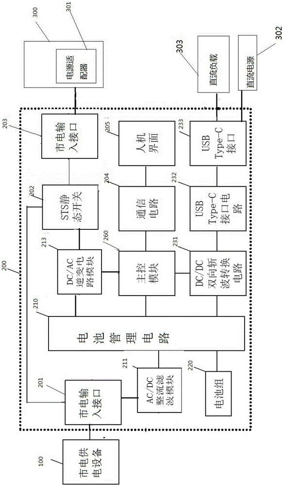
[0027] Such as figure 1 As shown, the novel uninterruptible power supply 200 is used to transmit the AC power provided by the mains power supply equipment 100 to the power consumption equipment 300 . The electric device 300 is a device driven by direct current. The electrical device 300 is provided with a power adapter 301 internally or externally. The power adapter 301 converts AC power into DC power for use. According to the novel uninterruptible power supply 200 of the present invention, it is provided with a mains power input interface 201 , a static switch 202 connected to the mains power input interface 201 , and an AC output interface 203 connected to the static switch 202 . The power adapter 301 is electrically connected to the AC output interface 203 . The mains power supply device 100 provides AC power to the power adapter 301 through the mains input interface 201 , the static switch 202 and the AC output interface 203 .

[0028] The novel uninterruptible power s...

Embodiment 2

[0044] Such as Figure 4 As shown, the novel uninterruptible power supply 200 is used to transmit the AC power provided by the mains power supply equipment 100 to the power consumption equipment 300 . The electric device 300 is a device driven by direct current. The electrical device 300 is provided with a power adapter 301 internally or externally. The power adapter 301 converts AC power into DC power for use. According to the novel uninterruptible power supply 200 of the present invention, it is provided with a mains power input interface 201 , a static switch 202 connected to the mains power input interface 201 , and an AC output interface 203 connected to the static switch 202 . The power adapter 301 is electrically connected to the AC output interface 203 . The mains power supply device 100 provides AC power to the power adapter 301 through the mains input interface 201 , the static switch 202 and the AC output interface 203 .

[0045] The novel uninterruptible power ...


PUM


Abstract

The invention discloses a novel uninterruptible power supply. The novel uninterruptible power supply is characterized by comprising a storage battery, a battery management circuit, and also comprises a direct current input and output circuit, wherein the storage battery is used for storing electric energy and externally outputting the electric energy; the battery management circuit is used for controlling the charging and discharging of the storage battery; the direct current input and output circuit is connected with the storage battery through the battery management circuit, used for externally outputting the direct current voltage of the storage battery, and also used for transmitting an external direct current voltage to the storage battery for charging the storage battery. The novel uninterruptible power supply provided by the invention has alternating current and direct current input dual electric power supplementing mechanisms; a battery pack can be charged by an alternating current mains supply as well as by direct current; and meanwhile, the novel uninterruptible power supply also has the alternating current and direct current output dual electric power supply functions.

Description

technical field [0001] The present invention relates to a novel uninterruptible power supply. Background technique [0002] UPS (Uninterruptible Power Supply) is set up to prevent power outages in the power grid and realize uninterrupted power supply. It is a system device that connects the battery with the host inverter to realize the conversion of DC power into AC power. It is used to provide stable and uninterrupted power supply for medical equipment, computer network system, communication base station system, and power electronic equipment. The three functions of UPS are: voltage stabilization, filtering, and uninterrupted. When the grid has power supply, it has the function of voltage stabilization and filtering to eliminate or weaken the interference of the external grid to the electrical equipment and ensure the normal and stable operation of the equipment. When the grid is powered off, it can realize zero-delay power supply switching through the internal reaction me...

Claims


Application Information

Patent Timeline
Patent Type & Authority Applications(China)
IPC IPC(8): H02J7/00H02J7/02H02J9/06
Inventor 谢芳吉陈庆全
Owner TOGOWIN TECH CO LTD
Why Eureka
Try Eureka