Rotor, magnetic steel fixing structure thereof, and motor

A fixed structure, magnetic steel technology, applied in the direction of magnetic circuit shape/style/structure, magnetic circuit, electrical components, etc., can solve the problems of easily damaged rotor magnetic circuit structure, complicated rotor production, difficult process, etc., to reduce processing. Process flow, simplified production, the effect of simplified production process

Inactive Publication Date: 2016-11-16
ZHUHAI GREE REFRIGERATION TECH CENT OF ENERGY SAVING & ENVIRONMENTAL PROTECTION
View PDF8 Cites 9 Cited by
  • Summary
  • Abstract
  • Description
  • Claims
  • Application Information

AI Technical Summary

Problems solved by technology

[0004] In the above magnetic steel fixing structure, the radial positioning of the magnetic steel 13 needs to be provided with threaded holes on the circumferential side wall of the rotor core 12. Increase the process of opening threaded holes, resulting in more complicated production of the entire rotor and lower production efficiency
[0005] In addition, opening threaded holes inward from the outer circular surface of the rotor core 12 is more difficult to process, and it is easier to damage the rotor magnetic circuit structure.

Method used


Image

  • Rotor, magnetic steel fixing structure thereof, and motor
  • Rotor, magnetic steel fixing structure thereof, and motor
  • Rotor, magnetic steel fixing structure thereof, and motor

Examples


Embodiment Construction

[0043] The following will clearly and completely describe the technical solutions in the embodiments of the present invention with reference to the accompanying drawings in the embodiments of the present invention. Obviously, the described embodiments are only some of the embodiments of the present invention, not all of them. Based on the embodiments of the present invention, all other embodiments obtained by persons of ordinary skill in the art without making creative efforts belong to the protection scope of the present invention.

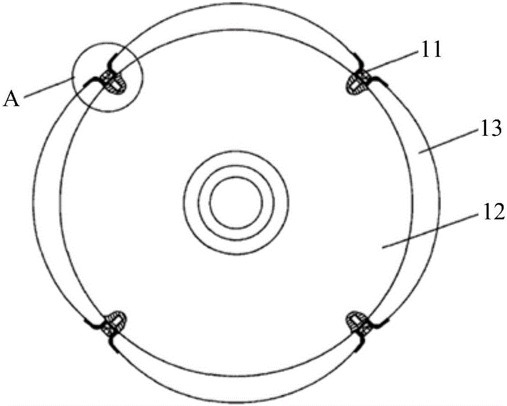
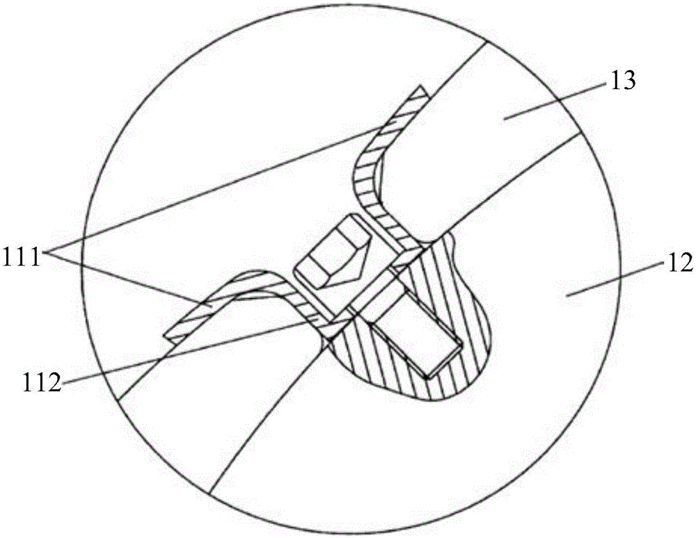
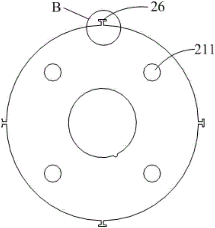
[0044] Such as Figure 3-11 As shown, the magnetic steel fixing structure of the rotor provided by the embodiment of the present invention includes: a rotor core 21, and the magnetic steels 23 distributed sequentially along the circumferential direction of the rotor core 21 are arranged between two adjacent magnetic steels 23 The limit piece 25. It can be understood that there is a gap between two adjacent magnetic steels 23 .

[0045] The abov...


PUM


Abstract

The present invention relates to a rotor, a magnet steel fixing structure thereof, and a motor. The motor magnet steel fixing structure includes a rotor core, magnet steels sequentially distributed in the circumferential direction of the rotor core, and stoppers located between two adjacent magnet steels, wherein each stopper includes a connecting portion and two pressing plates both fixedly connected with the connecting portion, the two pressing plates are respectively pressed on two adjacent magnet steels, and the connecting portion is in positioning connection with the rotor core in a radial direction through a concave-convex cooperative structure. In the magnet steel fixing structure, the connecting portion is in positioning connection with the rotor core in a radial direction through a concave-convex cooperative structure, and the structure required by the concave-convex cooperative structure can be formed in a rotor core punching process, so that compared with the prior art, a processing flow is reduced, the rotor core production process is simplified, thereby the production of a whole rotor is simplified, and rotor production efficiency is improved.

Description

technical field [0001] The invention relates to the technical field of permanent magnet motors, and more specifically, relates to a rotor, a magnetic steel fixing structure thereof, and a motor. Background technique [0002] At present, permanent magnet motors usually use adhesives such as glue to directly paste the magnetic steel on the surface of the rotor core. Adhesives often contain toxic substances, which can cause harm to the human body if exposed to them for a long time; secondly, manual operation is often used to paste magnets, and the thickness of glue application cannot be guaranteed to be uniform. The product consistency and reliability are poor, and the application thickness is uneven, which directly affects The gap between the stator and the rotor affects the performance of the motor; in addition, the adhesive needs to be kept at a certain temperature for a long time before it can be cured, and the manufacturing efficiency is low. [0003] In order to reduce t...

Claims


Application Information

Patent Timeline
Patent Type & Authority Applications(China)
IPC IPC(8): H02K1/27
CPCH02K1/27H02K2213/03H02K1/2781
Inventor 高东东
Owner ZHUHAI GREE REFRIGERATION TECH CENT OF ENERGY SAVING & ENVIRONMENTAL PROTECTION
Why Eureka
Try Eureka