Motor rotor for compressor, motor for compressor, and compressor

A motor rotor and compressor technology, applied in the field of compressors, can solve the problems of reduced motor characteristics of compressors, reduced oil-liquid separation effect, and reduced oil volume, etc., so as to inhibit the inflow of oil, inhibit agitation, and ensure oil volume Effect

Inactive Publication Date: 2016-11-16
GUANGDONG MEIZHI COMPRESSOR
View PDF9 Cites 1 Cited by
  • Summary
  • Abstract
  • Description
  • Claims
  • Application Information

AI Technical Summary

Problems solved by technology

[0002] When the compressor is running at high speed, the balance weight will stir the refrigerant gas on the side of the compression mechanism (that is, the side of the motor facing the compression mechanism), causing the refrigerant gas on the side of the anti-compression mechanism (that is, the side of the motor facing away from the compression mechanism) The separation effect of the oil contained in the gas is reduced, and the refrigerant gas containing the oil is discharged into the refrigeration cycle system, reducing the amount of oil in the oil pool in the compressor
In addition, in order to return the oil separated from the refrigerant gas on the side of the anti-compression mechanism to the side of the compression mechanism, it is necessary to increase the area of ​​the notch of the motor stator, which degrades the motor characteristics of the compressor.

Method used


Image

  • Motor rotor for compressor, motor for compressor, and compressor
  • Motor rotor for compressor, motor for compressor, and compressor
  • Motor rotor for compressor, motor for compressor, and compressor

Examples


Embodiment Construction

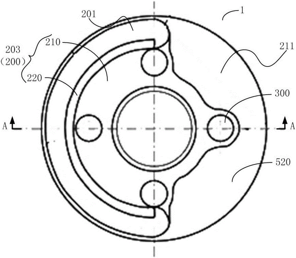
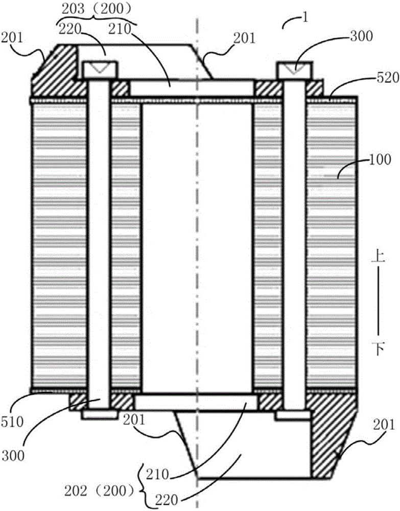
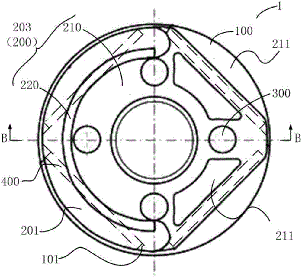
[0032] Embodiments of the present invention are described in detail below, examples of which are shown in the drawings, wherein the same or similar reference numerals designate the same or similar elements or elements having the same or similar functions throughout. The embodiments described below by referring to the figures are exemplary only for explaining the present invention and should not be construed as limiting the present invention.

[0033] In describing the present invention, it should be understood that the terms "length", "thickness", "upper", "lower", "inner", "outer", "clockwise", "counterclockwise", "axial ", "radial", "circumferential" and other indicated orientations or positional relationships are based on the orientations or positional relationships shown in the drawings, which are only for the convenience of describing the present invention and simplifying the description, rather than indicating or implying the referred device Or elements must have a certa...


PUM


Abstract

The invention discloses a motor rotor for a compressor, a motor for the compressor, and the compressor. The motor rotor for the compressor comprises a rotor iron core and at least one balance block, wherein the rotor iron core is provided with a compression end and a decompression end in an axial direction; the balance block comprises a mounting part and a balance part; the mounting part is mounted on at least one end plane of the compression end and the decompression end of the rotor iron core; the balance part is connected with the surface, opposite to the end plane, of the mounting part, and can extend in the circumference direction of the rotor iron core; and an inclined plane which is tilted relative to the end plane is arranged between the outer end plane and the outer circumferential surface of the balance part. According to the motor rotor for the compressor provided by the invention, the motor rotor is particularly applicable to high-rotary-speed operation; under a condition that the motor characteristic of the compressor is ensured, the separation effect of oil and liquid contained in a refrigerant gas can be improved; the oil liquid flowing in a refrigerating and circulating system can be restrained; and the oil amount in the compressor can be ensured.

Description

technical field [0001] The invention relates to the technical field of compressor manufacturing, in particular to a motor rotor for a compressor, a motor for a compressor having the motor rotor for a compressor, and a motor for a compressor having the motor rotor for a compressor compressor. Background technique [0002] When the compressor is running at high speed, the balance weight will stir the refrigerant gas on the side of the compression mechanism (that is, the side of the motor facing the compression mechanism), causing the refrigerant gas on the side of the anti-compression mechanism (that is, the side of the motor facing away from the compression mechanism) The separation effect of the oil contained in the gas is reduced, and the refrigerant gas containing the oil is discharged into the refrigeration cycle system, reducing the amount of oil in the oil pool in the compressor. In addition, in order to return the oil separated from the refrigerant gas on the anti-com...

Claims


Application Information

Patent Timeline
Patent Type & Authority Applications(China)
IPC IPC(8): H02K7/04H02K1/27H02K21/16F04C23/02
Inventor 坂柳智司张巍王玲
Owner GUANGDONG MEIZHI COMPRESSOR
Why Eureka
Try Eureka