Optical time-domain reflectometer based on DSP

An optical time domain reflectometer and optical switch technology, applied in the field of communication, can solve problems such as low transmission accuracy, poor anti-interference ability, inconvenient fault location and branch transmission detection, and achieve high transmission accuracy, strong anti-interference ability, and high speed fast effect

Inactive Publication Date: 2016-11-16
泉州市科茂利通智能科技有限公司
View PDF0 Cites 0 Cited by
  • Summary
  • Abstract
  • Description
  • Claims
  • Application Information

AI Technical Summary

Problems solved by technology

However, the existing optical time domain reflectometers often have low transmission accuracy and poor anti-interference ability, and the traditional OTDR is aimed at the point-to-point structure, which brings inconvenience to fault location and branch transmission detection. Aiming at the above problems, a special Optical Time Domain Reflectometer Based on DSP

Method used


Image

  • Optical time-domain reflectometer based on DSP
  • Optical time-domain reflectometer based on DSP
  • Optical time-domain reflectometer based on DSP

Examples


Embodiment Construction

[0017] The following will clearly and completely describe the technical solutions in the embodiments of the present invention with reference to the accompanying drawings in the embodiments of the present invention. Obviously, the described embodiments are only some, not all, embodiments of the present invention. Based on the embodiments of the present invention, all other embodiments obtained by persons of ordinary skill in the art without making creative efforts belong to the protection scope of the present invention.

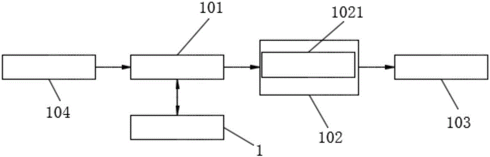
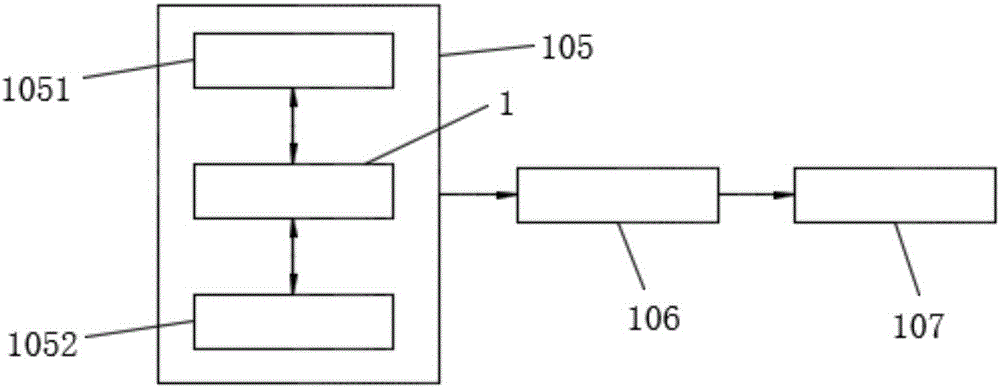
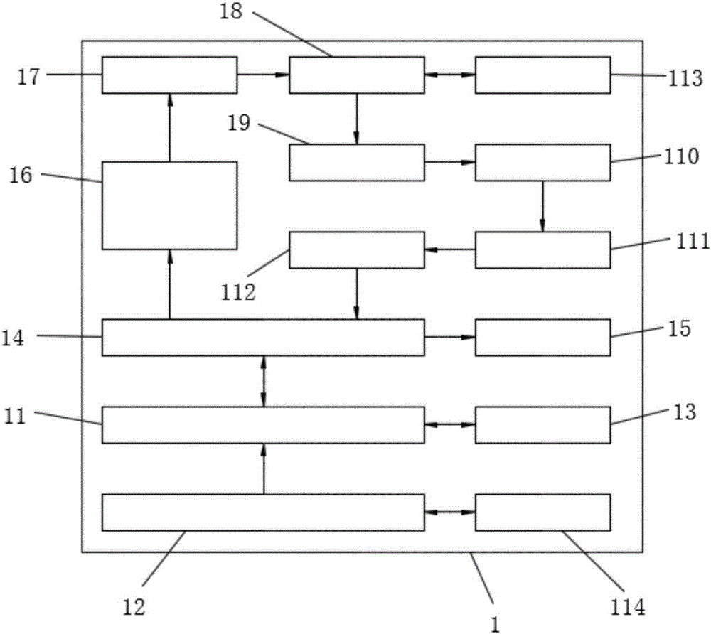
[0018] see figure 1 and image 3 , the first technical solution provided by the present invention: a DSP-based optical time domain reflectometer, including an OTDR unit 1, the OTDR unit 1 includes a DSP unit 11, and the DSP unit 11 is connected to a power supply unit 12 through an electric conductor And operation unit 13, described DSP unit 11 is connected with FPGA unit 14 by electrical conductor, and described FPGA unit 14 is connected with display unit 15 ...


PUM


Abstract

The invention discloses an optical time-domain reflectometer based on a DSP. The optical time-domain reflectometer comprises an OTDR unit; the OTDR unit comprises a DSP unit; furthermore, the DSP unit is connected to a power supply unit and an operation unit through an electric conductor; the DSP unit is connected to a FPGA unit through the electric conductor; the FPGA unit is connected to a display unit through the electric conductor; the FPGA unit is connected to a laser emission control unit, a laser unit, an optical fibre coupler unit, an APD unit, a signal amplification unit, an A/D conversion unit and a FIFO unit through the electric conductor; the laser emission control unit, the laser unit, the optical fibre coupler unit, the APD unit, the signal amplification unit, the A/D conversion unit and the FIFO unit are sequentially connected electrically; furthermore, the FIFO unit is connected with the FPGA unit through the electric conductor; and the optical fibre coupler unit is connected to an optical fibre unit to be tested through the electric conductor. By means of the optical time-domain reflectometer based on the DSP disclosed by the invention, a detection result can be obtained more accurately and rapidly; furthermore, the specific position information of a fault point can be obtained accurately; and the optical time-domain reflectometer is relatively high in practicability, high in transmission precision, rapid in speed and high in anti-interference capability, and can be suitable for many changes in a network.

Description

technical field [0001] The invention relates to the technical field of communication, in particular to a DSP-based optical time domain reflectometer. Background technique [0002] At present, with the continuous development of optical communication, an important branch of optical communication - Optical Fiber Communications (Optical Fiber Communications) is gradually replacing cables and microwave communications due to its advantages of wide transmission frequency bandwidth, high anti-interference and low signal attenuation. It has become the main transmission method in the world communication. Optical fiber communication is a communication method that uses light waves as a carrier and optical fiber as a transmission medium to transmit information from one place to another. It is called "wired" optical communication. Therefore, the performance of optical fiber directly affects the speed and distance of optical signal transmission. Lightning, earthquakes, and constructions ...

Claims


Application Information

Patent Timeline
Patent Type & Authority Applications(China)
IPC IPC(8): H04B10/071
CPCH04B10/071
Inventor 尹宏肖凯文何情
Owner 泉州市科茂利通智能科技有限公司
Why Eureka
Try Eureka