Eureka AIR delivers breakthrough ideas for toughest innovation challenges, trusted by R&D personnel around the world.

Indoor passive positioning method based on channel state information and support vector machine

A channel state information and support vector machine technology, applied in positioning, measuring devices, wireless communication, etc., can solve problems such as inaccurate positioning, increased computational complexity, and inability to accurately express the relationship between position coordinates and signal fingerprints, etc., to improve passive The effect of positioning accuracy, reducing computational complexity, and accurate dimensions

Inactive Publication Date: 2016-11-16
UNIV OF ELECTRONICS SCI & TECH OF CHINA
View PDF4 Cites 45 Cited by
  • Summary
  • Abstract
  • Description
  • Claims
  • Application Information

AI Technical Summary

Problems solved by technology

Since the indoor area is often large and the environment is complex, the unified dependency relationship used in the entire positioning area cannot accurately express the relationship between position coordinates and signal fingerprints, and thus cannot accurately locate
In order to ensure the positioning accuracy, a large amount of fingerprint data will be collected in a large positioning area, resulting in an increase in computational complexity

Method used


Image

  • Indoor passive positioning method based on channel state information and support vector machine
  • Indoor passive positioning method based on channel state information and support vector machine
  • Indoor passive positioning method based on channel state information and support vector machine

Examples


Embodiment Construction

[0027] A two-level indoor passive positioning method based on CSI and SVM, the process is as follows figure 1 As shown, the specific implementation steps are as follows:

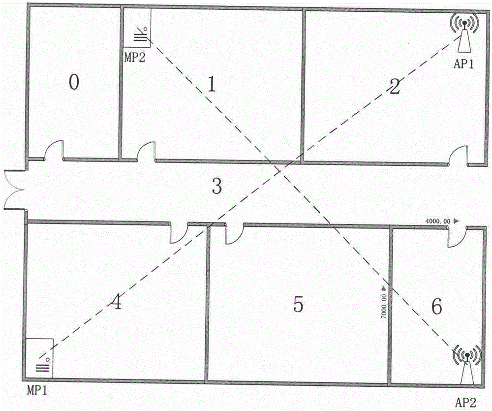
[0028] 1) Environmental deployment: Wi-Fi-based passive positioning requires indoor coverage of Wi-Fi signals. It is necessary to deploy several wireless access points AP (support 802.11n), several monitoring points MP, and one for processing and analyzing monitoring point collection data processor. Place APs and MPs in the environment in a diagonally crossing manner. For a schematic diagram of the layout, see figure 2 , MP1 receives data from AP1, and MP2 receives data from AP2. The positioning area is divided into several sub-areas according to the indoor building structure, and several positioning reference points in each sub-area are determined.

[0029] 2) CSI raw data collection: In the training phase, people stay at each reference point, and each MP collects several pieces of CSI raw data from the...


PUM


Abstract

The invention discloses an indoor passive positioning method based on channel state information and a support vector machine. The method comprises the following steps: firstly preprocessing the acquired channel state information data, performing de-noising and smoothness through the adoption of a density-based spatial clustering of applications with noise and a weight-based moving average algorithm, and then using the principal component analysis algorithm to extract the features. The data after the preprocessing and feature-extracting can reflect the signal change more accurately and the dimension is greatly reduced. The passive positioning adopts two-stage positioning. In the training stage, the large positioning space is divided into sub-regions, the support vector machine classification and regression model is established for each sub-region so as to acquire a statistic model for accurately representing the nonlinear relationship between the position and the signal. The two-stage positioning firstly determines the sub-regions through the classification of the support vector machine, and the precision position is determined in the sub-region through the regression of the support vector machine. The method disclosed by the invention has the beneficial effects that the passive positioning can be performed in the absence of the active participation of the target, and the indoor positioning precision is improved to sub-meter level.

Description

technical field [0001] The invention relates to the field of indoor positioning, in particular to an indoor high-precision passive positioning method based on channel state information. Background technique [0002] Wi-Fi-based wireless local area network has been widely deployed indoors, and it can also provide positioning services while providing data transmission services. Wi-Fi-based indoor positioning solutions do not need to build special hardware facilities, make full use of existing wireless networks, and expand the application range of low-cost positioning to buildings and indoors. At present, most Wi-Fi indoor positioning technologies adopt the active positioning method, that is, to locate the electronic device carried by the target, scan the surrounding Wi-Fi wireless access points (Access Point, AP, usually a wireless router) and their signal strength, and based on this Make a location estimate. However, in many cases, the positioning target does not carry elec...

Claims


Application Information

Patent Timeline
IPC IPC(8): H04W64/00G01S5/02
CPCH04W64/006G01S5/0252G01S5/0257
Inventor 周瑞陈结松罗磊张洋铭卢帅
Owner UNIV OF ELECTRONICS SCI & TECH OF CHINA
Why Eureka
Eureka Blog
Learn More