Rotatable street lamp control system

A street lamp control and street lamp technology, applied in energy-saving control technology, electric lamp circuit layout, lighting devices, etc., can solve the problems of inability to accurately control street lamps, inconvenience for people to travel, resource cost, etc., to achieve good application value and improve utilization. rate, ensure the effect of lighting brightness

Inactive Publication Date: 2016-11-16
ANHUI ZHUOYUE ELECTRIC
View PDF7 Cites 6 Cited by
  • Summary
  • Abstract
  • Description
  • Claims
  • Application Information

AI Technical Summary

Problems solved by technology

[0003] However, the existing street lamp control device cannot accurately control the street lamps. The street lamps are turned on and off at a fixed time, and cannot respond to changes in the external optical fiber. They are still illuminated when the light is strong or stop when the optical fiber is dark. The lighting is grouped together, which cannot meet the needs of people to use street lighting. It not only causes inconvenience to people's travel, but also has a certain resource cost.
In addition, the existing street lamps and their lighting directions are generally fixed. Under different weather conditions, different light intensities and angles are required to enable pedestrians to see the road conditions clearly. However, the existing conservative design cannot Very good to meet people's lighting needs

Method used


Image

  • Rotatable street lamp control system
  • Rotatable street lamp control system

Examples


Embodiment Construction

[0019] Below in conjunction with specific embodiment, further illustrate the present invention. These examples are only for illustrating the present invention and are not intended to limit the scope of the present invention.

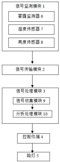
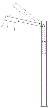
[0020] Such as figure 1 and figure 2 As shown, a rotatable street lamp control system of a preferred implementation of the present invention includes a signal monitoring module 1, a signal transmission module 2, a signal processing module 3, a control terminal 4, and a street lamp 5, and the signal monitoring module 1 includes a haze monitoring module. device 6, a humidity sensor 7, a brightness sensor 8, and the haze monitor 6 transmits the monitored haze condition in the air where the street lamp is located to the signal processing module 3 through the signal transmission module 2, and the humidity sensor 7. Transmit the signal of whether the monitored surrounding environment is rainy or sunny to the signal processing module 3 through the signal tra...


PUM


Abstract

The invention provides a rotatable street lamp control system. The rotatable street lamp control system comprises a signal monitoring module, a signal transmission module, a signal processing module, a control terminal and a street lamp, wherein the signal monitoring module comprises a haze monitor, a humidity sensor and a brightness sensor; the haze monitor, the humidity sensor and the brightness sensor are used for transmitting a haze condition, a rain and snow condition and a brightness condition in the environment to the signal processing module through the signal transmission module respectively; the signal processing module is used for processing and converting obtained signal data, and then signals are transmitted to the control terminal; and the control terminal is used for sending out commands to the street lamp so as to realize control for the health condition of the street lamp as well as street lamp brightness and angle. The control system can monitor the weather and brightness condition of the environment where the street lamp is in real time, the rotation angle of the street lamp is controlled according to practical situations, the utilization rate of the street lamp is improved to the maximum extent, safe operation of the street lamp is guaranteed, and the control system has relatively good application value.

Description

technical field [0001] The invention relates to a rotatable street lamp control system. Background technique [0002] Street lights refer to lamps installed on utility poles, along streets, roads, etc. for lighting. They are municipal public facilities closely related to people's daily life. At present, the lighting control and management of most cities in the country adopts the traditional mode. The street light switch is carefully and independently controlled by each street light controller device of the power distribution cabinet. , roads, etc. for lighting. [0003] However, the existing street lamp control device cannot accurately control the street lamps. The street lamps are turned on and off at a fixed time, and cannot respond to changes in the external optical fiber. They are still illuminated when the light is strong or stop when the optical fiber is dark. The lighting is grouped together, which cannot meet the needs of people to use street lamps for lighting. It...

Claims


Application Information

Patent Timeline
IPC IPC(8): H05B37/02H05B47/105H05B47/11
CPCH05B47/105H05B47/11H05B47/19Y02B20/40
Inventor 王连明王有锁周星星赵立军
Owner ANHUI ZHUOYUE ELECTRIC
Why Eureka
Try Eureka