Precise sensing control method and night light of infrared induction night light
A technology of infrared induction and induction control, applied in the field of induction lamps, can solve problems such as malfunction, no decorative function, lighting, etc., to achieve the effect of eliminating directionality, preventing irritation, and soft color and light
- Summary
- Abstract
- Description
- Claims
- Application Information
AI Technical Summary
Problems solved by technology
Method used
Image
Examples
Embodiment 1
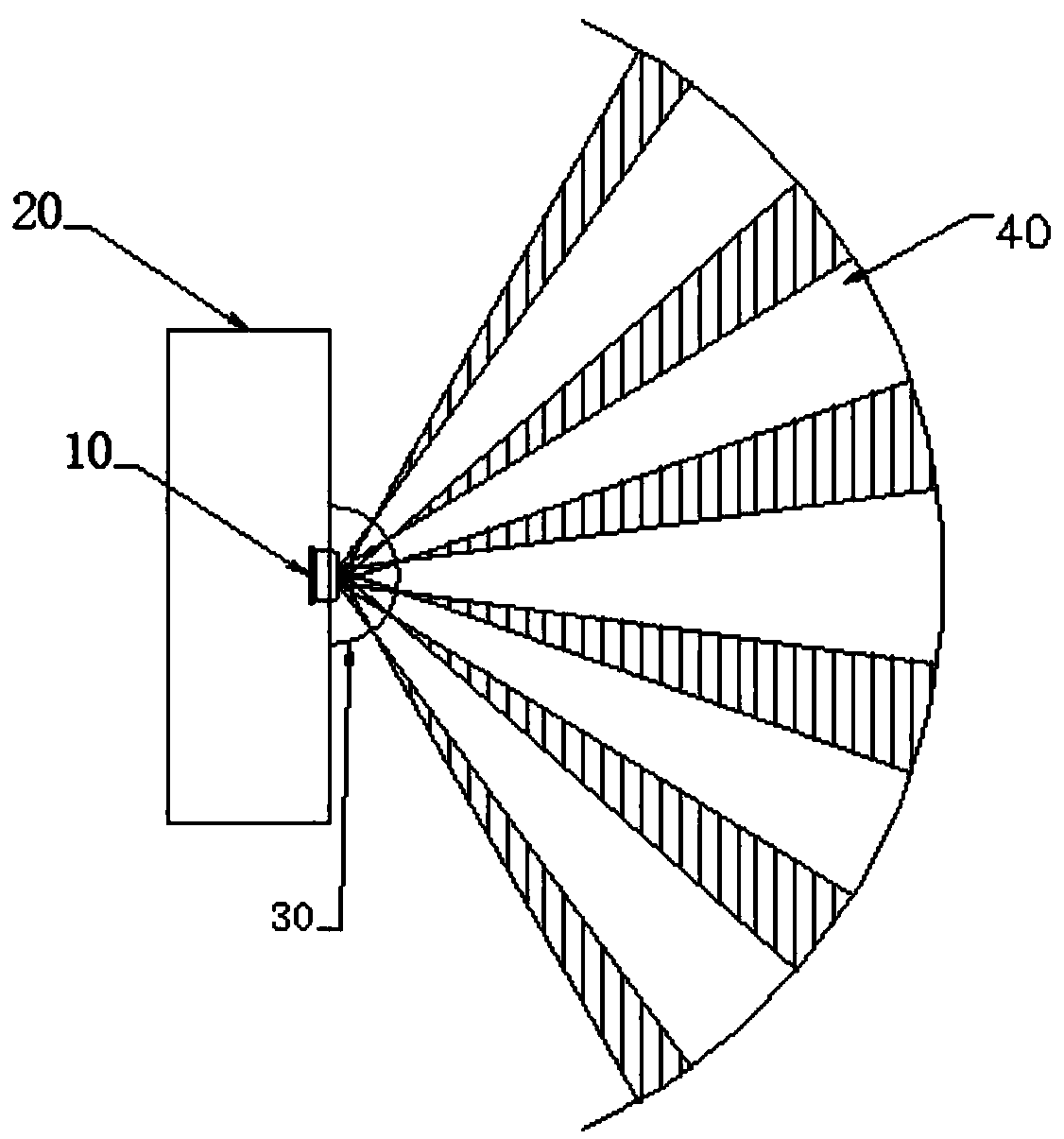
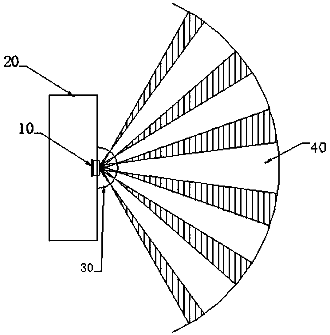
[0060] Please refer to Figure 11 to Figure 18 According to an embodiment of the present invention, a precise sensing control method for an infrared sensing night light comprises the following steps:
[0061] (1) An infrared induction night light is set, which includes a lamp housing 1, at least one LED light source 2, a human body sensing unit, and a control unit, and the human body sensing unit includes at least one infrared lens 3 and a pyroelectric infrared sensor 4;
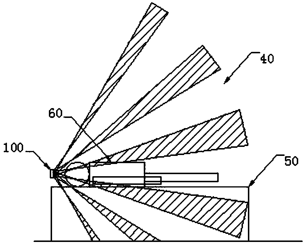
[0062] (2) The pyroelectric infrared sensor 4 is horizontally arranged in the lamp housing 1, so that the infrared lens 3 is embedded on the lamp housing 1 and exposed to the outside, so that the formed infrared sensing area is inclined upward to the lamp housing 1 to extend;
[0063] (3) Cooperate the infrared lens 3 and the pyroelectric infrared sensor 4 so that the pyroelectric infrared sensor 4 passes through the infrared lens 3 to form a specific sensing area 5: the specific sensing area 5 is marked w...
Embodiment 2
[0073] Please refer to Figure 19 to Figure 21 , the main difference between this embodiment and Embodiment 1 is:
[0074] The step 2) is to embed the at least one infrared lens 3 on the outer surface of the lamp housing 1. When a plurality of infrared lenses are combined, the infrared lenses are arranged horizontally along the outer surface of the lamp housing;
[0075] In step 3), the infrared sensing area formed by the infrared lens 3 and the pyroelectric infrared sensor 4 extends obliquely upward from the side of the lamp housing 1, and the sensing line 51 at the outermost edge of the sensing area 5 is connected to the The included angle between the axial centerline 11 of the lamp housing 1 is 50°-60°.
[0076] In this embodiment, the infrared lens 3 may be a combination of multiple infrared lenses.
[0077] like Figure 20 As shown, the infrared lens 3 can be a cylindrical infrared lens, and the cylindrical infrared lens is arranged on the outer surface of the lamp hou...
Embodiment 3
[0080] Please refer to Figure 22 to Figure 28 , the main difference between this embodiment and Embodiment 1 is: in the step 1), the LED light source 2 is arranged in the lamp housing 1, and makes it distribute light upwards or downwards; A switch unit is also provided on the surface of the lamp housing of the lamp, and the switch unit is connected to the control unit; the switch unit is a touch switch or a mechanical switch; The lampshade 12 and the lamp body 13 are provided with transparent or translucent decorative materials inside or outside the transparent lampshade 12 .
[0081] In this embodiment, the function of the switch unit is: through the switch input, the LED light source can be controlled to turn on, extinguish and change the brightness. Only when the LED light source is turned off, the infrared induction night light function works.
[0082] Specifically, such as Figure 23 , Figure 24 As shown, the LED light source 2 is for downward light distribution, and...
PUM
 Abstract
Description
Claims
Application Information
 - R&D
- Intellectual Property
- Life Sciences
- Materials
- Tech Scout
- Unparalleled Data Quality
- Higher Quality Content
- 60% Fewer Hallucinations
Browse by: Latest US Patents, China's latest patents, Technical Efficacy Thesaurus, Application Domain, Technology Topic, Popular Technical Reports.
© 2025 PatSnap. All rights reserved.Legal|Privacy policy|Modern Slavery Act Transparency Statement|Sitemap|About US| Contact US: help@patsnap.com


