Combine harvester

A technology for combine harvesters and harvesting devices, which is applied to harvesters, agricultural machinery and implements, and threshing equipment, and can solve problems such as the reduction of grain stalk delivery capacity

Inactive Publication Date: 2016-11-16
YANMAR CO LTD
View PDF8 Cites 2 Cited by
  • Summary
  • Abstract
  • Description
  • Claims
  • Application Information

AI Technical Summary

Problems solved by technology

However, in the conventional front rotor, the blades did not catch the grain stalks, and the conveyance capacity of the grain stalks decreased.

Method used


Image

  • Combine harvester
  • Combine harvester
  • Combine harvester

Examples


Embodiment Construction

[0048] First, the combine harvester 100 will be briefly described.

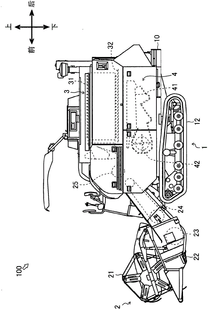
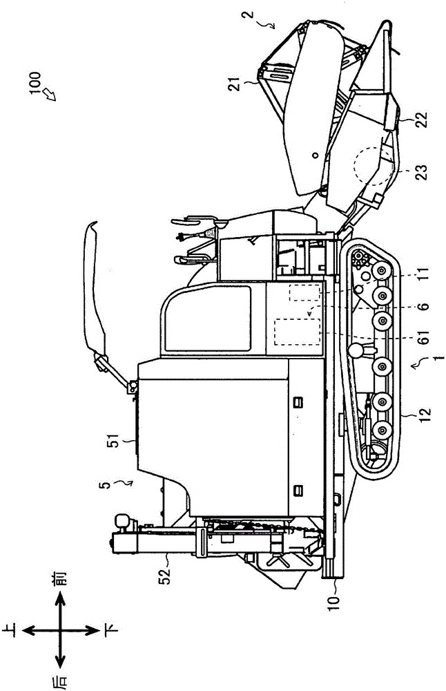
[0049] figure 1 The left side of the combine harvester 100 is shown. figure 2 The right side of the combine harvester 100 is shown. The figure shows the front-back direction and the up-down direction of the combine harvester 100.

[0050] The combine harvester 100 is mainly composed of a traveling device 1 , a harvesting device 2 , a threshing device 3 , a sorting device 4 , a storage device 5 and a power device 6 .

[0051] The traveling device 1 is provided below the chassis frame 10 . The travel device 1 is composed of a transmission 11 and a pair of left and right crawler belt devices 12·12. The transmission 11 transmits power of a diesel engine 61 described later to the crawler belt devices 12·12. Crawler belt apparatus 12*12 runs the combine 100 in the front-back direction. Moreover, crawler belt apparatus 12*12 turns the combine 100 to the left-right direction.

[0052] Harvesting device 2 is i...


PUM


Abstract

A combine harvester (100) provided with a reaping device (2) for reaping grain culms, a threshing device (3) for threshing the reaped grain culms, and a sorting device (4) for sorting grains (G) from chaff (C), wherein the sorting device (4) is structured such that a chaff sieve (412) is arranged behind a feed pan (411) and a separator (414) is arranged above the chaff sieve (412), and the separator (414) is arranged behind and above the feed pan (411), thereby forming a passageway (P) through which the chaff (C) passes from the feed pan (411) to the chaff sieve (412).

Description

technical field [0001] The present invention relates to combine harvesters. Background technique [0002] Conventionally, the combine which reaps a grain stalk while traveling, and threshes the reaped grain stalk is known (for example, refer patent document 1). Such a combine includes a sorting device for sorting grains from threshing grains. The sorting device is provided with a sieve called a chaff sieve, and the grains are sorted by swinging the chaff sieve. [0003] However, the combine provided with the separator is known (for example, refer patent document 2). In a related combine harvester, the separator catches all the threshed grain from which a coarse sorting of the kernels takes place. However, the structure in which the separator catches all the threshed grains and roughly sorts them has problems in that the sorting speed of the grains is slowed down, and the harvesting operation in the field is slowed down. Therefore, the combine harvester which maintained t...

Claims


Application Information

Patent Timeline
IPC IPC(8): A01F12/30A01D61/00A01F12/10
CPCA01F12/44
Inventor 乙仓进北冈治正吉武雄一郎平松康平中畠章博佐村木仁
Owner YANMAR CO LTD
Why Eureka
Try Eureka