
A multi-output two-stage dc/dc converter using a composite pcb board transformer

A PCB board and converter technology, which is applied in the field of multi-output two-stage DC/DC converters, can solve the problem that the design method of multi-output power transformers is not described, does not involve power-on and power-off sequence control and failover, and cannot achieve multiple problems such as precise control of output converters, to achieve the effect of increasing power supply varieties, reducing volume and weight, and improving control functions

Active Publication Date: 2014-04-09
BEIJING SATELLITE MFG FACTORY
View PDF3 Cites 8 Cited by
  • Summary
  • Abstract
  • Description
  • Claims
  • Application Information

AI Technical Summary

Problems solved by technology

[0004] Generally speaking, the currently disclosed multi-output DC / DC converter still has the following deficiencies: (1) it simply points out that the front-stage converter and the rear-stage converter are multi-phase converters, and does not point out the specific Converter topology type; (2) only mentions the control method of the front-end converter and the rear-end converter, does not explain the design method of the multi-output power transformer, and cannot use one power transformer to achieve up to eight outputs; (3) It is impossible to accurately control the outputs of each output of the multi-output converter, so that the output voltage of each output can meet the high-precision requirements within the full load range; Power-off sequence control and failover; (5) No redundant primary circuit and backup circuit

Method used


Image

  • A multi-output two-stage dc/dc converter using a composite pcb board transformer
  • A multi-output two-stage dc/dc converter using a composite pcb board transformer
  • A multi-output two-stage dc/dc converter using a composite pcb board transformer

Examples


Embodiment Construction

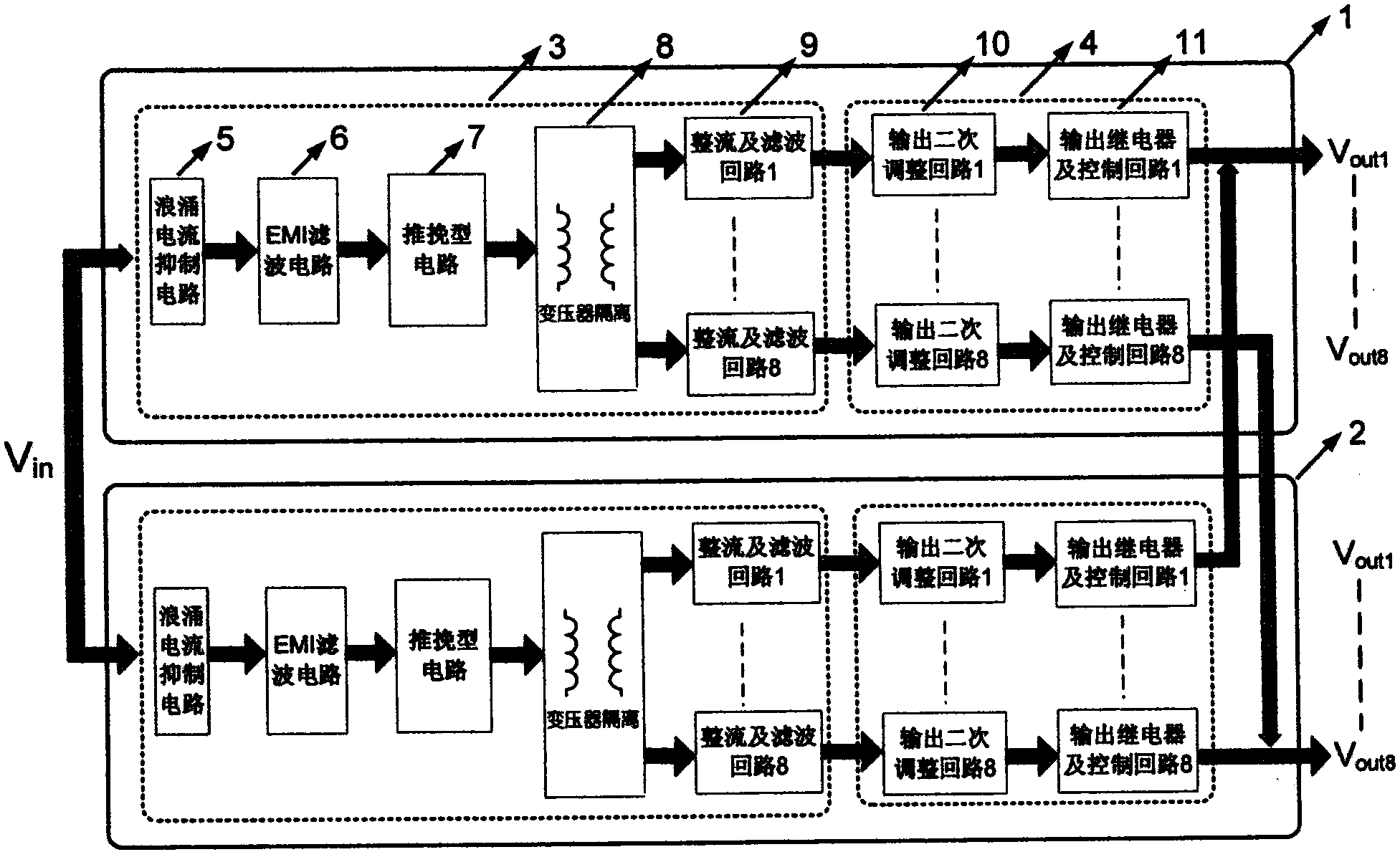
[0030] The circuit structure of the multi-output two-stage DC / DC converter of the present invention is as follows figure 1As shown, the multi-output two-stage DC / DC converter includes a redundant primary circuit 1 and a backup circuit 2, and the circuit structures and control methods are identical. Taking the master circuit 1 as an example, it includes a cascaded front-stage converter 3 and a rear-stage converter 4 .

[0031] The pre-stage converter 3 converts the bus voltage into N output voltages through the push-pull circuit 7 and transformer isolation circuit 8 after being protected by the surge current suppression circuit 5 and filtered by the EMI input filter circuit 6, and each output voltage After smoothing and filtering by the rectification and filtering circuit 9, output to the rear-stage converter 4; each output secondary adjustment circuit in the rear-stage converter 4 receives the smooth-filtered voltage output by the previous stage, and adjusts the voltage accord...


PUM


Abstract

A multi-output two-stage DC / DC converter using a composite PCB board-type transformer, including a main circuit (1), and the main circuit includes cascaded pre-stage converters (3) and post-stage converters (4) ; After the pre-stage converter (3) protects the busbar voltage through the surge current suppression circuit (5) and filters the EMI input filter circuit (6), the busbar voltage is reduced by the push-pull circuit (7) and the transformer isolation circuit (8). Transformed into N output voltages, each output voltage is respectively rectified and smoothed by the filter circuit (9) and then output to the rear-stage converter (4); the output secondary adjustment circuit in the rear-stage converter (4) receives the previous-stage The output smoothed and filtered voltage adjusts the input voltage according to the magnitude of the output current of each channel, and the adjusted voltage is output under the timing control of the output relays of each channel and the control loop (11). The invention overcomes the deficiencies of the prior art, can be applied to various spacecraft, and has many output channels and high reliability.

Description

technical field [0001] The invention belongs to the general technical field of aerospace, and relates to a multi-output two-stage DC / DC converter applied to power supply of aerospace electronic equipment. Background technique [0002] The rapid development of spacecraft puts forward higher and higher requirements for its power supply system, the power supply varieties of spacecraft power supply system are also increasing, and the development trend of multi-output power supply is becoming more and more obvious. At present, most of the imported DC / DC converters used in domestic spacecraft are single-output converters. Well-known foreign aerospace-grade power supply manufacturers can only provide a limited number of types of multi-output DC / DC converters, and all of them are specific voltage, Compared with the domestic market, the multi-output converter with specific power is less flexible. [0003] Currently, there are public multi-output DC / DC converters. For example, the p...

Claims


Application Information

Patent Timeline
IPC IPC(8): H02M3/155H02M3/10
Inventor 任海英李廷中雷卫军
Owner BEIJING SATELLITE MFG FACTORY
Learn More