
Fly-killing device with air cleaning function

A technology that cleans the air and functions. It can be used in devices for capturing or killing insects, animal husbandry, and applications. It can solve the problem of single function of the fly killer, and achieve the effect of easy cleaning, no environmental pollution, and reduced odor.

Pending Publication Date: 2016-11-23
成都米利得科技有限公司
View PDF0 Cites 1 Cited by
  • Summary
  • Abstract
  • Description
  • Claims
  • Application Information

AI Technical Summary

Problems solved by technology

[0002] Fly killer lamps can be divided into electric shock type and sticky trap type according to the function of killing. The principle is to lure flies with light, to lure flies close to the lamp tube of the fly killer lamp, and to make the insects contact the high-voltage electric fence or sticky trap near the fly killer lamp. The fly paper is electrocuted or stuck to achieve the purpose of killing flies, but the current fly killer has a single function and cannot meet multiple needs. The present invention expands the function of the fly killer and is more suitable for the life of modern people need

Method used

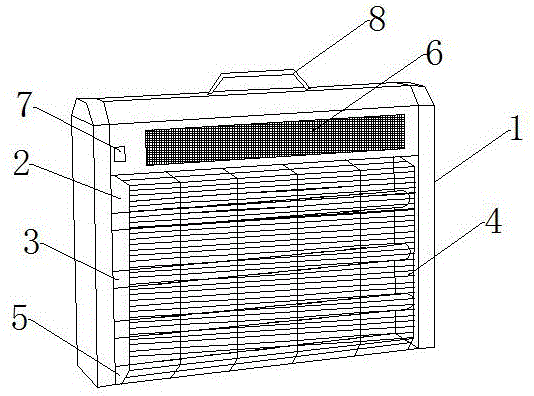

Image

  • Fly-killing device with air cleaning function

Examples


Embodiment 1

[0019] Such as figure 1 As shown, a fly killer with the function of cleaning air includes a box body 1, a cavity 2 is provided at the bottom of the box body 1, a grid 4 covering the cavity 2 is provided on the box body 1, and a Insect trap lamp 3 is arranged, and the top of described casing 1 is provided with fresh air board 6, and described insect lamp 3 can be the lamp tube that is arranged in parallel, also can be the light bulb that hangs, and described air fresh board 6 is arranged on The top of the cavity is not connected to the power grid 4. When the present invention works, the insect trap lamp 3 can attract flies to fly over. When the fly flies to the insect trap lamp 3, it needs to cross the power grid 4. When the fly touches the electrified When the power grid 4 is on, it will be electrocuted to kill the flies, but the accumulation of flies after death will easily produce peculiar smells. At this time, the air freshening plate 6 arranged on the top of the box body 1...

Embodiment 2

[0021] This embodiment is further defined on the basis of the above embodiments, the air freshening plate 6 is an activated carbon plate, the activated carbon plate can absorb the peculiar smell and harmful bacteria in the air, and remove the peculiar smell purely physically without pollution.

[0022] Other parts of this embodiment are the same as those of the foregoing embodiment, and will not be repeated here.

Embodiment 3

[0024] This embodiment is further defined on the basis of the above embodiments, the grid 4 is a high-voltage grid, which reduces the survival rate of flies after being electrocuted, and the high voltage is 4K volts.

[0025] Other parts of this embodiment are the same as those of the foregoing embodiment, and will not be repeated here.


PUM


Abstract

The invention discloses a fly-killing device with an air cleaning function. The fly-killing device comprises a box body, wherein a cavity is formed in the lower part of the box body, an electric net covering the cavity is formed in the box body, a light trap is arranged in the cavity, an air refreshing plate is arranged at the upper part of the box body and is an activated plate, and the electric net is a high-voltage electric net; a base plate is arranged at the bottom of the box body and is movably connected with a side plate of the box body, a power supply switch is further arranged at the upper part of the box body, and a lifting handle is arranged on the top of the box body. The fly-killing device has the beneficial effects that flies are killed by virtue of the high-voltage electric net, so that the operation is simple and efficient, the environment is not polluted, and meanwhile, the peculiar smell is reduced; the additionally arranged activated carbon plate can be used for adsorbing the peculiar smell in air close to the fly-killing device and refreshing air; the detachable base plate is movably connected with the side plate, and killed flies can fall to the ground, so that the cleaning is convenient.

Description

technical field [0001] The invention relates to the field of fly killing equipment, in particular to a fly killing device with the function of cleaning air. Background technique [0002] Fly killer lamps can be divided into electric shock type and sticky trap type according to the function of killing. The principle is to lure flies with light, to lure flies close to the lamp tube of the fly killer lamp, and to make the insects contact the high-voltage electric fence or sticky trap near the fly killer lamp. The fly paper is electrocuted or stuck to achieve the purpose of killing flies, but the current fly killer has a single function and cannot meet multiple needs. The present invention expands the function of the fly killer and is more suitable for the life of modern people need. Contents of the invention [0003] The object of the present invention is to provide a fly killer with simple structure, effective fly killer, convenient cleaning and fresh air. [0004] The pre...

Claims


Application Information

Patent Timeline
Patent Type & Authority Applications(China)
IPC IPC(8): A01M1/04A01M1/22A61L9/16
CPCA01M1/04A01M1/223A61L9/16
Inventor 杨素杰
Owner 成都米利得科技有限公司
Learn More