Ball storage rack

A technology of ball storage and connecting parts, applied in the field of ball storage racks, which can solve the problems of loose balls, easy movement of ball storage racks, and inability to place the ball storage racks on the ground stably, so as to reduce friction and improve stability Effect

Inactive Publication Date: 2016-11-23
天津天宝华科科技股份有限公司
View PDF1 Cites 0 Cited by
  • Summary
  • Abstract
  • Description
  • Claims
  • Application Information

AI Technical Summary

Problems solved by technology

But there is a problem in this ball storage stand: the universal wheel is fixedly connected with the fixed base, which causes the ball storage stand to be unable to be stably placed on the ground, so that the ball storage stand is easy to move under the action of external force. When the ball storage rack collides with other objects, it is easy to cause the balls to scatter

Method used


Image

  • Ball storage rack
  • Ball storage rack
  • Ball storage rack

Examples


Embodiment Construction

[0027] The following are specific embodiments of the present invention and in conjunction with the accompanying drawings, the technical solutions of the present invention are further described, but the present invention is not limited to these embodiments.

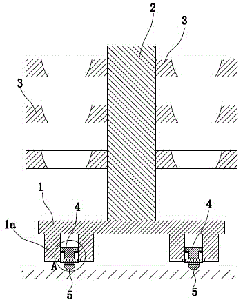
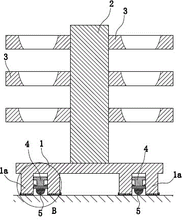
[0028] like figure 1 and image 3 As shown, the ball storage rack is composed of a base plate 1, a support rod 2, a fixed ring 3, a sliding column 4, and universal balls 5.

[0029] Wherein, the substrate 1 is in the shape of a long plate and arranged along the horizontal direction. The support rod 2 is vertically arranged on the upper side of the base plate 1 and in this embodiment, the support rod 2 is fixed with the base plate 1 by welding. There are several fixed rings 3 and they are all fixed on the support rod 2. In actual use, balls are placed in the fixed rings 3 for storage.

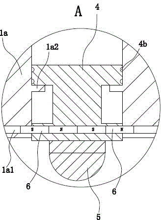
[0030] like figure 1 As shown, the lower side of the base plate 1 has a cylindrically protruding connecting portion 1 a, and there are ...


PUM


Abstract

The invention provides a ball storage rack and belongs to the technical field of machines. The ball storage rack solves the problem that an existing ball storage rack is not good in stability. The ball storage rack comprises a base plate and a supporting rod vertically arranged on the upper side of the base plate. A plurality of fixing rings are fixedly connected to the supporting rod, cylindrical protruding connection parts are arranged on the lower side face of the base plate, and the two connection parts are located on the two sides of the supporting rod. Each connection part is internally provided with a sliding column capable of sliding up and down in an inserted mode, a strip-shaped lock hole penetrates through the upper end of each sliding column in the radial direction, the two ends of each lock hole are connected with two magnetic columns respectively in an inserted mode, the adjacent ends of every two magnetic columns are opposite in polarity, the two ends of each connection part are provided with connection holes corresponding to the corresponding lock holes, the other ends of every two magnetic columns are inserted into the corresponding connection holes, the lower ends of the sliding columns extend out of the connection parts, universal balls are fixedly connected to the lower end faces of the sliding columns, when the sliding columns slide upwards, the universal balls are located in the connection parts, and the base plate and the sliding columns are made of a plastic material. The ball storage rack has the advantage of being good in stability.

Description

technical field [0001] The invention belongs to the technical field of machinery and relates to a ball storage rack. Background technique [0002] Among the many sports equipment, balls occupy a place, but they are also the most difficult to store. This is because the balls are very smooth and easy to roll after being placed, which is not convenient for storage. Most of the balls are now stored in boxes or frames, which are not easy to store and select. [0003] For the above problems, people have realized the shortcomings and made improvements, such as a freely movable ball storage stand disclosed in the Chinese patent library [application number: 201120045600.1; authorization announcement number: CN 201929406 U], including fixing and supporting Functional fixed base, the fixed base is fixed with an upright fixed plate, and the fixed plate is provided with a plurality of ball fixing devices for fixing balls; the ball fixing device includes a fixed fixed plate A buckle and...

Claims


Application Information

Patent Timeline
Patent Type & Authority Applications(China)
IPC IPC(8): A47B81/00A47B91/00A47B91/06
Inventor 于学刚
Owner 天津天宝华科科技股份有限公司
Why Eureka
Try Eureka