
swirl slug catcher

A trap and plug flow technology, which is applied in the direction of chemical instruments and methods, separation methods, and dispersed particle separation, can solve the problems of TP plate separation load, hydraulic impact, and clogged liquid level, etc., so as to reduce the total investment of the project, Save operating costs and alleviate the effect of slug flow

Active Publication Date: 2018-10-30
GANSU LANPEC TECH +2
View PDF6 Cites 0 Cited by
  • Summary
  • Abstract
  • Description
  • Claims
  • Application Information

AI Technical Summary

Problems solved by technology

Severe slug flow will cause a series of problems such as hydraulic shock, blockage and liquid level fluctuations to the oil-gas separation equipment at the end of the pipeline and subsequent process devices, making it difficult for downstream process devices to work normally
[0003] The inlet of the current slug catcher usually adopts an inlet distributor or a degassing plate, which relies on collision and gas-liquid density difference for gravity separation, which requires a long residence time and a large enough separation space and liquid storage space, and the gas space The separation load of the TP plate is heavy and the separation efficiency is low

Method used


Image

  • swirl slug catcher
  • swirl slug catcher
  • swirl slug catcher

Examples


Embodiment Construction

[0020] In order to further disclose the technical solution of the present invention, below in conjunction with accompanying drawing of description, elaborate in detail through embodiment:

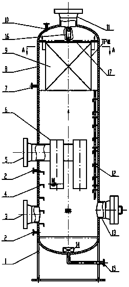
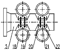
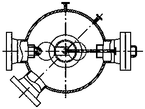
[0021] refer to figure 1 , 2 , 3, 4, the present invention relates to an oil-gas mixed transport slug catcher device for catching slug flow, which mainly consists of a housing 8, a TP plate assembly 9, a swirl cylinder 6, a vortex breaker 14, Downcomer 12, gas outlet 11, liquid outlet 3, sewage outlet 15, safety valve 7, liquid level gauge / transmitter 2, pressure gauge 10, and manhole 13.

[0022] A swirl slug catcher, comprising a housing, a gas inlet is provided in the tangential direction in the middle of the housing, a swirl cylinder 6 is installed in the housing 8 at the gas inlet 5, and the upper gas space in the housing 8 A TP plate assembly 9 with radial channels is installed inside. The slug flows through the gas inlet 5 and enters each swirl tube 18 of the swirl cylinder 6 alon...


PUM


Abstract

The invention discloses a cyclone slug capturer which comprises a shell. A gas inlet is formed in the central tangential direction of the shell, a cyclone cylinder is mounted at the gas inlet in the shell, a TP plate component with a radial channel is mounted in an upper gas space in the shell, and the capturer is of a vertical structure. By the aid of the cyclone slug capturer, gas-liquid separation efficiency can be improved, the influence of oil-gas mixed transportation pipeline slug flow on production is effectively eliminated, stable production processes of follow-up technologies are facilitated, and construction cost is reduced.

Description

technical field [0001] The invention relates to a treatment device for slug flow in an oil-gas mixed transportation pipeline, which is suitable for collecting and eliminating slug flow in surface gathering and transportation projects of oil and gas fields. Background technique [0002] With the development of ocean, land oil and gas fields, and large condensate gas fields, the multiphase mixed transportation process has been continuously developed. In the multiphase mixed transportation process and long-distance gas transportation pipelines, slug flow usually occurs. Severe slug flow will cause a series of problems such as hydraulic shock, blockage and liquid level fluctuations to the oil-gas separation equipment at the end of the pipeline and subsequent process devices, making it difficult for downstream process devices to work normally. [0003] The inlet of the current slug catcher usually adopts an inlet distributor or a degassing plate, which relies on collision and gas...

Claims


Application Information

Patent Timeline
Patent Type & Authority Patents(China)
IPC IPC(8): B01D45/06B01D45/08B01D45/16
CPCB01D45/06B01D45/08B01D45/16
Inventor 张尚文文晓龙周少斌冯森森王海鹏武艳波杨作万刘学虎
Owner GANSU LANPEC TECH
Learn More