Flood-discharge tunnel-based combined energy dissipater synchronizing flood discharge and power generation

A technology of synchronous combination and flood discharge tunnel, which is applied in water conservancy projects, sea area engineering, coastline protection, etc., can solve the problems of unsuitable flood discharge tunnels for power generation and energy dissipation, and increased project investment, so as to improve the downstream ecological environment, increase energy dissipation efficiency, Reduce the effect of surface tumbling

Inactive Publication Date: 2014-10-15
HOHAI UNIV
View PDF7 Cites 3 Cited by
  • Summary
  • Abstract
  • Description
  • Claims
  • Application Information

AI Technical Summary

Problems solved by technology

This has resulted in an excessive increase in project investment, which has also fallen into the development idea of ​​conventional flood discharge, power generation and water diversion
[0006] In addition, there is also a kind of existing technology which is to rebuild the structure of the surface hole overflow dam or the surface hole spillway into a flood discharge power generation structure. However, this kind of flood discharge power generation and energy dissipation hydropower station is only applicable to The surface hole spillway is transformed, and it is not suitable to use the structural form of the spillway tunnel for power generation and energy dissipation

Method used


Image

  • Flood-discharge tunnel-based combined energy dissipater synchronizing flood discharge and power generation
  • Flood-discharge tunnel-based combined energy dissipater synchronizing flood discharge and power generation
  • Flood-discharge tunnel-based combined energy dissipater synchronizing flood discharge and power generation

Examples


Embodiment Construction

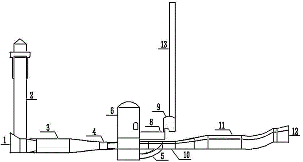
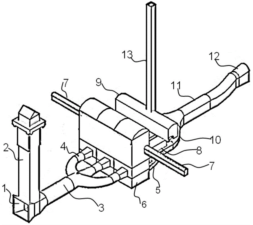
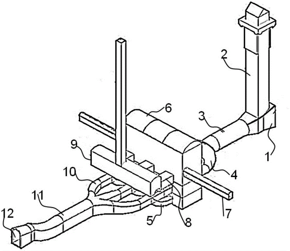
[0018] like Figure 1 to Figure 5 As shown, the present invention is based on the synchronous combination energy dissipation device for flood discharge power generation of flood discharge tunnel, which mainly includes sequentially arranged water inlet tower, underground main powerhouse, contact hole, main transformer room with transformer, shaft, draft pipe, tail water branch holes and tailwater holes. A water inlet is arranged under the water inlet tower, and is connected with the hydroelectric generator in the underground main powerhouse through a pressurized water flow tunnel and a diversion branch tunnel. The positional relationship and connection relationship of the above structures are shown in the figure, and the positional relationship can be adjusted according to the actual situation.

[0019] The water inlet tower 2 is provided with a water inlet 1, which leads the water in the flood discharge tunnel to the underground main powerhouse 6 through the pressurized water...


PUM


Abstract

The invention discloses a flood-discharge tunnel-based combined energy dissipater synchronizing flood discharge and power generation. The energy dissipater comprises a water inlet tower, an underground main powerhouse, a contact hole, a main transformer chamber with a transformer, a vertical shaft, a tail water pipe, a tail water branch tunnel and a pressure-free tail water tunnel. The water inlet tower is provided with a water inlet, the water inlet tower guides water in a flood-discharge tunnel into the underground main powerhouse through a pressured water flow tunnel, a water turbine power generator is disposed in the underground main powerhouse, water flows generate power and dissipate energy through the water turbine power generator, current is guided to a ground step-up substation through the contact hole, the main transformer chamber and the vertical shaft, and the water flows flow into a downstream water channel through the tail water pipe, the tail water branch tunnel and the pressure-free tail water tunnel. The energy dissipater has the advantages that the energy of the flood-discharge water flows in the tunnel is converted into electric energy so as to achieve energy dissipation, energy of surplus water is fully utilized, the flow speed of the tail water acquired after surplus water power generation is quite low, surface rotation of downstream water is reduced greatly, downstream ecological environments can be improved effectively, and the dissipater is widely applicable to in-tunnel flood discharge of different flow rates.

Description

technical field [0001] The invention belongs to the field of hydraulic engineering, in particular to an energy dissipation structure. Background technique [0002] Generally speaking, the threat of floods is solved by setting up spillways and spillway tunnels or overflow dams and spillway bottom holes, while water resources are utilized by setting up conventional underground powerhouses or ground-type powerhouses, and flood discharge buildings are set up separately from power generation buildings , independent of each other, which causes a huge waste of flood discharge energy during the flood period. [0003] In order to reduce flood discharge and increase power generation, it is usually necessary to increase the height of the dam and increase the storage capacity of the reservoir, which also increases the scale of the project and increases the investment of the project, making it difficult to meet the requirements of economic evaluation. In order to make full use of hydrop...

Claims


Application Information

Patent Timeline
Patent Type & Authority Applications(China)
IPC IPC(8): E02B8/06
Inventor 刘依松任旭华张继勋
Owner HOHAI UNIV
Why Eureka
Try Eureka