Water flushing device with sighting device
A sight and water flushing technology, which is applied to chemical instruments and methods, liquid cleaning methods, cleaning methods and appliances, etc., can solve the problems of incomplete cleaning of dead corners of power equipment, and achieve the goal of improving convenience and accuracy Effect
- Summary
- Abstract
- Description
- Claims
- Application Information
AI Technical Summary
Problems solved by technology
Method used
Image
Examples
Embodiment 1
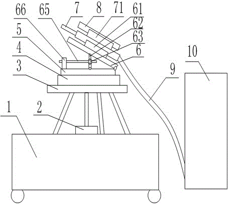
[0040] Such as figure 1 As shown, the water flushing device with a sight includes a turntable 4, the turntable 4 is connected with the power output shaft of the motor 2, a height-adjustable bracket is arranged on the turntable 4, a high-pressure spray gun 7 is arranged on the bracket, and a high-pressure spray gun 7 A sight 8 is arranged on it, and the high-pressure spray gun 7 is connected to the water tank 10 through a water pipe 9; A fixed column 66 is provided, and an adjusting rod 65 is arranged on the fixed column 66 in a rotating manner. Two connecting rods 62 are hinged on the adjusting rod 65, one of which is hinged with the inside of the fixed plate 5, and the other connecting rod 62 is connected with the inclined plate. 6 inner hinged.
Embodiment 2
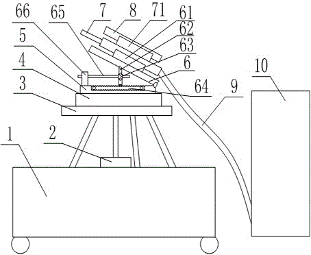
[0042] Such as figure 2 As shown, the water flushing device with a sight includes a turntable 4, the turntable 4 is connected with the power output shaft of the motor 2, a height-adjustable bracket is arranged on the turntable 4, a high-pressure spray gun 7 is arranged on the bracket, and a high-pressure spray gun 7 A sight 8 is arranged on it, and the high-pressure spray gun 7 is connected to the water tank 10 through a water pipe 9; A fixed column 66 is provided, and an adjusting rod 65 is rotatably arranged on the fixed column 66. Two connecting rods 62 are hinged on the adjusting rod 65. One of the connecting rods 62 is hinged to the inner side of the swash plate 6, and the other connecting rod 62 is not hinged. A sawtooth structure is provided at the end, and a toothed belt 64 is provided on the inner side of the fixing plate 5 , and the sawtooth structure and the toothed belt 64 cooperate with each other.
Embodiment 3
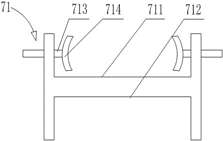
[0044] Such as figure 1 , figure 2 As shown, this embodiment is based on Embodiment 1 or Embodiment 2. The adjusting rod 65 is sleeved with a fixed cylinder 63, and the adjusting rod 65 is hinged on the fixed cylinder 63; the high-pressure spray gun 7 is arranged on the first In the draw-in slot 61, the first draw-in slot 61 is arranged on the swash plate 6; the aimer 8 is arranged in the second draw-in slot 71, and the second draw-in slot 71 is arranged on the high-pressure spray gun 7; The rotating disk 4 is placed on the fixed frame 3, the fixed frame 3 is provided with a through hole for passing through the power output shaft of the motor 2, the fixed frame 3 is provided with an annular groove, and the bottom of the rotating disk 4 is provided with a ring that matches the annular groove. universal ball; the fixed frame 3 is placed on the mobile trolley 1.
PUM
 Abstract
Description
Claims
Application Information
 - R&D
- Intellectual Property
- Life Sciences
- Materials
- Tech Scout
- Unparalleled Data Quality
- Higher Quality Content
- 60% Fewer Hallucinations
Browse by: Latest US Patents, China's latest patents, Technical Efficacy Thesaurus, Application Domain, Technology Topic, Popular Technical Reports.
© 2025 PatSnap. All rights reserved.Legal|Privacy policy|Modern Slavery Act Transparency Statement|Sitemap|About US| Contact US: help@patsnap.com


