
Feeding machine

A feeding machine and rack technology, which is applied to conveyors, conveyor objects, transportation and packaging, etc., can solve problems such as leakage, frequent maintenance, and large volume, achieve convenient operation, realize automatic feeding, and save labor costs. Effect

Inactive Publication Date: 2016-11-23
李丽开
View PDF5 Cites 0 Cited by
  • Summary
  • Abstract
  • Description
  • Claims
  • Application Information

AI Technical Summary

Problems solved by technology

However, the use of hydraulic control requires a hydraulic motor and corresponding oil tanks and pipelines, which are large in size, require frequent maintenance, and have the risk of leakage, while servo drives have advantages in terms of operating speed, control accuracy, overload capacity, and low-speed operation stability. obvious advantage

Method used


Image

  • Feeding machine
  • Feeding machine
  • Feeding machine

Examples


Embodiment Construction

[0014] The preferred embodiments of the present invention will be described in detail below in conjunction with the accompanying drawings, so that the advantages and features of the invention can be more easily understood by those skilled in the art, so as to define the protection scope of the present invention more clearly.

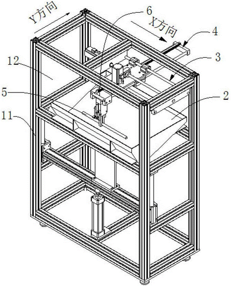
[0015] see figure 1 , the embodiment of the present invention includes: a feeding machine, which is mainly used for automatic feeding of processed workpieces. The specific structure and working principle of the feeding machine of the present invention will be introduced below by loading metal sheets.

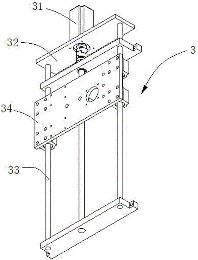
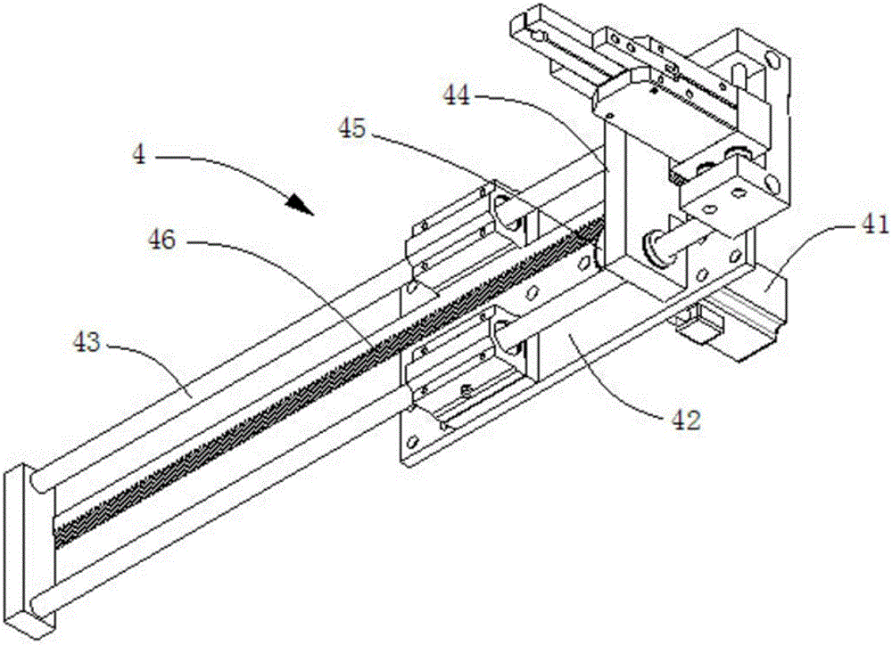
[0016] like figure 1 As shown, a loading machine disclosed by the present invention includes a frame 1, a silo 2, an X-direction drive mechanism 3, a Y-direction drive mechanism 4, and a scraper rod 5, and the frame 1 is used as a support for the entire body , which is built by a plurality of brackets 11, generally in the shape of a cuboid, and a silo acc...


PUM


Abstract

The invention discloses a feeding machine. The feeding machine comprises a rack, a stock bin, an X-direction drive mechanism, a Y-direction drive mechanism and a material scraping rod. The stock bin is fixed into the rack, the X-direction drive mechanism is fixed to the rack and located above the stock bin, the Y-direction drive mechanism is perpendicularly located on the X-direction drive mechanism and fixedly connected with the rack, the material scraping rod is in sliding connection with the Y-direction drive mechanism through a connecting rod; the matched drive manner of an air cylinder and a lead screw is adopted, workpieces are driven to be automatically conveyed out in the horizontal direction and the vertical direction, automatic feeding of the workpieces is achieved, operation is convenient, manpower cost is saved, and the production machining efficiency is improved.

Description

technical field [0001] The invention relates to the field of feeding machinery and equipment, in particular to a feeding machine for realizing automatic loading of workpieces. Background technique [0002] The task of the loading machine is to separate the workpieces to be processed from the silo or stocker, and put them into the designated positions as required. The feeding mechanism is one of the main working mechanisms in automatic machinery. Its performance and degree of automation directly affect the production efficiency and quality of automatic machinery. [0003] For the feeding system of sheet metal, most of the previous designs used the form of hydraulic cylinders, which have simple control and high lifting force. However, the use of hydraulic control requires a hydraulic motor and corresponding oil tanks and pipelines, which are large in size, require frequent maintenance, and have the risk of leakage, while servo drives have advantages in terms of operating spee...

Claims


Application Information

Patent Timeline
IPC IPC(8): B65G47/04
CPCB65G47/04B65G2201/022
Inventor 李丽开
Owner 李丽开
Learn More