
Copper alloy cutting device

A cutting device and copper alloy technology, applied in shearing devices, metal processing equipment, metal processing machinery parts, etc., can solve the problems of affecting cutting efficiency and cutting quality, affecting the service life of the device, and failing to handle waste residues, etc. Material automation, saving time and improving service life

Pending Publication Date: 2021-04-09
江苏立一新材料科技有限公司
View PDF9 Cites 0 Cited by
  • Summary
  • Abstract
  • Description
  • Claims
  • Application Information

AI Technical Summary

Problems solved by technology

[0003] In the process of cutting copper alloy, the current cutting machine is not able to deal with the high temperature brought during work and the waste residue generated during cutting, which affects the service life of the device, and also pollutes the environment, causing a waste of resources, and Affect cutting efficiency and cutting quality

Method used


Image

  • Copper alloy cutting device
  • Copper alloy cutting device
  • Copper alloy cutting device

Examples


Embodiment 1

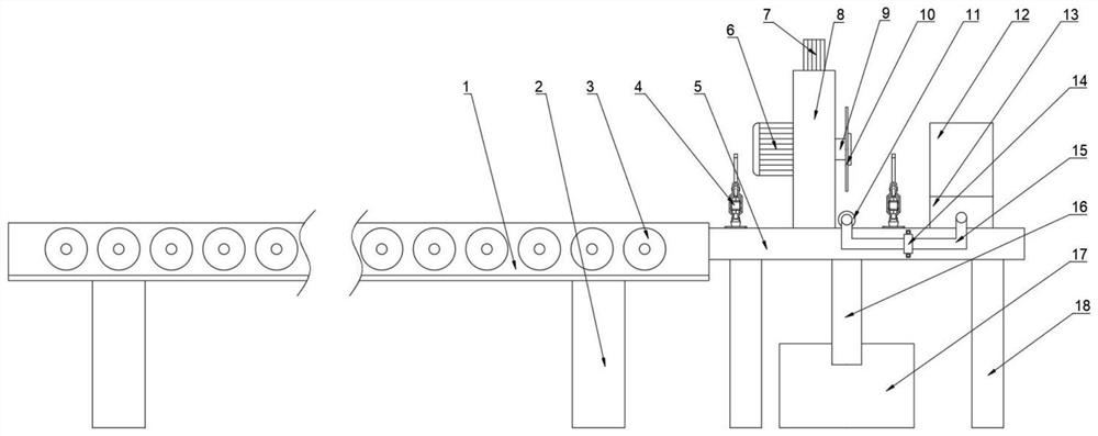
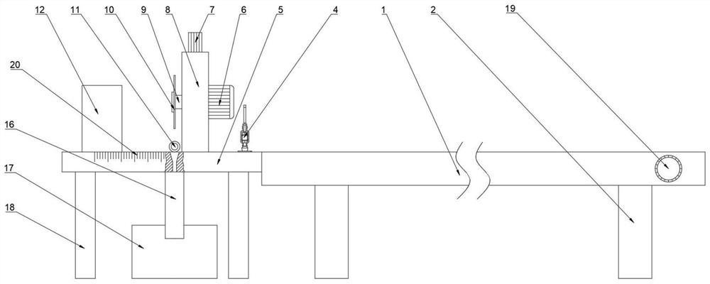
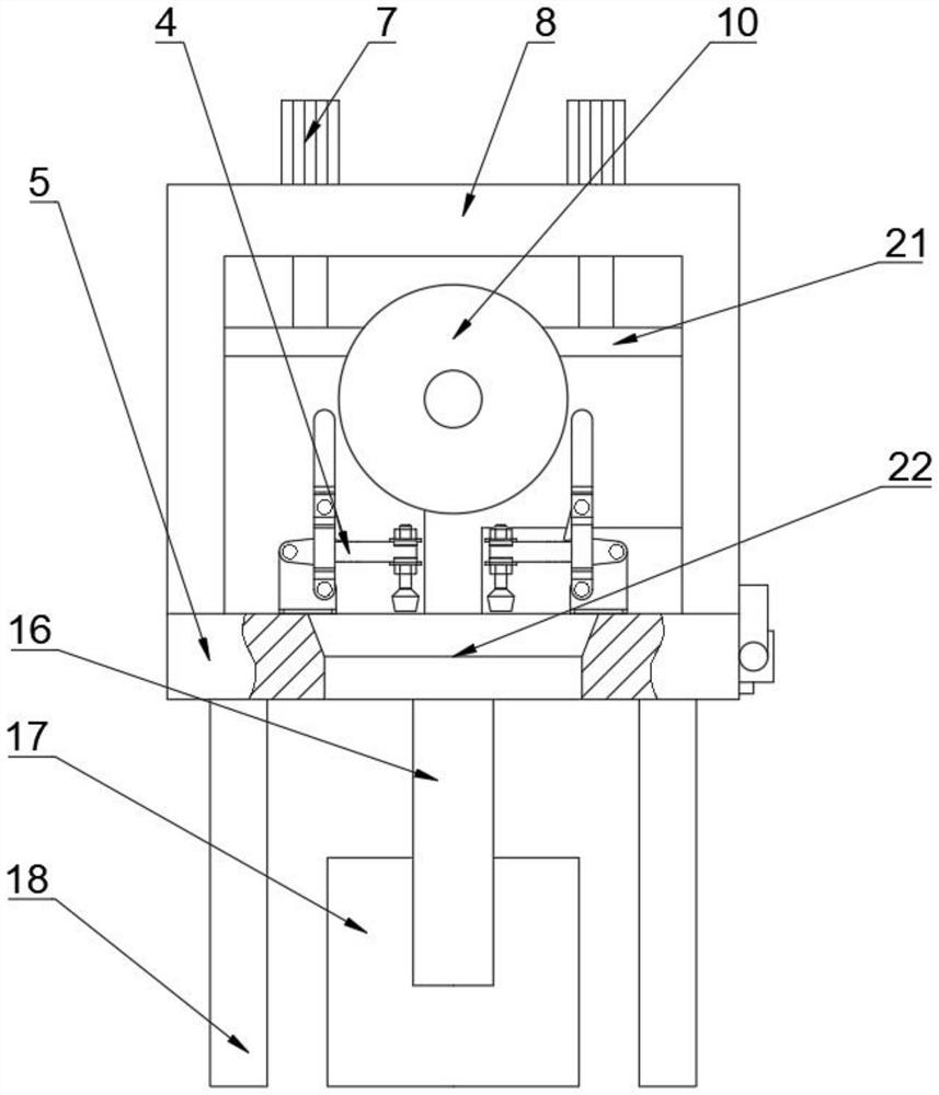
[0022] see Figure 1~3 , in Embodiment 1 of the present invention, a copper alloy cutting device includes a transport mechanism, a cutting mechanism, a cooling and dust removal mechanism, a quick clamp 4, a workbench 5 and legs 18;

[0023] The cooling and dedusting mechanism includes a nozzle 11, a water tank 12, a water pump 13, a baffle plate 14, a water pipe 15, a return pipe 16 and a sewage collection box 17. The water tank 12 is fixedly connected to the right side of the workbench 5, and the water pump 13 is fixedly connected to the In front of the right side of the workbench 5, the water pipe 15 is detachably connected to the water outlet of the water pump 13, and the baffle plate 14 is installed on the side of the workbench 5 by screws. The function of the baffle plate 14 is to fix the water pipe 15 to keep the water pipe 15 stable. 11 is fixedly connected to the water outlet end of the water pipe 15, and is arranged below the cutting wheel 10, and the return pipe 16 i...

Embodiment 2

[0026] see Figure 1~3 The main difference between this embodiment 2 and embodiment 1 is that the cutting mechanism includes a rotating motor 6, an electric push rod 7, a U-shaped plate 8, a rotating shaft 9 and a cutting wheel 10, and the U-shaped plate 8 is fixedly connected to the working On the upper surface of the table 5, the electric push rod 7 is fixedly connected above the U-shaped plate 8, and is slidably connected with the U-shaped plate 8. The bottom of the electric push rod 7 is fixedly connected with a connecting rod 21, and the rotating motor 6 is fixedly connected to the connecting rod. The lower surface of 21, and is connected with rotating shaft 9 transmissions, and the right end of rotating shaft 9 is fixedly connected with a cutting wheel 10; When starting to work, at first start rotating motor 6, under the effect of rotating motor 6, rotating shaft 9 begins to rotate, Thereby the cutting wheel 10 is driven to start rotating. At this time, the transport mec...


PUM


Abstract

The invention discloses a copper alloy cutting device, and relates to the technical field of copper alloy production. The copper alloy cutting device comprises a conveying mechanism, a cutting mechanism, a cooling and dust removing mechanism, a quick clamp, a workbench and supporting legs. the cooling and dust removing mechanism comprises a spray head, a water tank, a water pump, a baffle, a water pipe, a water return pipe and a sewage collecting box, the water tank and the water pump are fixedly connected to the right side of the workbench, the water pipe is connected to a water outlet of the water pump, the baffle is installed on the side face of the workbench, the spray head is fixedly connected to the water outlet end of the water pipe, the water return pipe is fixedly connected to the lower surface of the workbench, and the sewage collecting tank is arranged below the water return pipe. The copper alloy cutting device has the beneficial effects that the copper alloy cutting device is assisted by the cooling and dust removing mechanism during cutting of the cutting mechanism, spraying is carried out on a cutting part, through the spraying effect of the spray head, the high temperature brought by the cutting mechanism during working can be effectively reduced, waste residues generated during cutting can be removed, the service life of the device is prolonged, and meanwhile, the environmental protection requirement of the device is further improved.

Description

technical field [0001] The invention relates to the technical field of copper alloy production, in particular to a copper alloy cutting device. Background technique [0002] Copper alloy is a memory alloy with the color of gold, commonly known as brass, which is characterized by high density, easy filling, and good thermal conductivity. Among them, cast tin bronze has a wide crystallization temperature range, is prone to shrinkage defects, and is not strongly oxidized. , so that it is widely used in the field of mechanical processing. When copper alloy is produced and processed, it needs to be cut first to meet the processing requirements. [0003] In the process of cutting copper alloy, the current cutting machine is not able to deal with the high temperature brought during work and the waste residue generated during cutting, which affects the service life of the device, and also pollutes the environment, causing a waste of resources, and Affect cutting efficiency and cutt...

Claims


Application Information

Patent Timeline
Patent Type & Authority Applications(China)
IPC IPC(8): B23D19/00B23Q11/10B23Q11/00
CPCB23D19/00B23Q11/10B23Q11/0042
Inventor 韩建
Owner 江苏立一新材料科技有限公司
Learn More