Regenerator pore plate structure of catalytic cracking device

A technology of catalytic cracking device and orifice structure, which is applied in catalytic cracking, cracking, petroleum industry, etc.

Active Publication Date: 2016-11-23
LUOYANG ZHIDA PETROCHEM ENG
View PDF3 Cites 2 Cited by
  • Summary
  • Abstract
  • Description
  • Claims
  • Application Information

AI Technical Summary

Problems solved by technology

[0004] The purpose of the present invention is to solve the deficiencies of the prior art, and provide a regenerator orifice structure of a catalytic cracking unit with a new structure. The technical problem to be so...

Method used


Image

  • Regenerator pore plate structure of catalytic cracking device
  • Regenerator pore plate structure of catalytic cracking device
  • Regenerator pore plate structure of catalytic cracking device

Examples


Embodiment Construction

[0027] For further elaborating the technical means and effect that the present invention takes for reaching the intended invention purpose, below in conjunction with accompanying drawing and preferred embodiment, its specific implementation, structure to the regenerator orifice structure of the catalytic cracking unit that proposes according to the present invention , features and their effects are described in detail below.

[0028] see Figure 4-6 , which is a schematic diagram of the regenerator orifice structure of the catalytic cracking unit in the embodiment of the present invention. The regenerator orifice structure includes a flat cover head 1, a skirt 2 and a regenerator shell 3, wherein the flat cover head 1 is Cloth has wear-resisting short pipe 11. The upper end of the skirt 2 is fixedly connected with the flat head 1, and the upper end of the skirt 2 is connected with the flat head through a butt weld. The end of the lower end of the skirt 2 with the arc section...


PUM


Abstract

The invention relates to a regenerator pore plate structure of a catalytic cracking device. The regenerator pore plate structure of the catalytic cracking device comprises a flat head 1, a skirt 2 and a regenerator shell 3, wherein wear-resistant short pipes 11 are uniformly distributed on the flat head 1; the upper end of the skirt 2 and the flat head 1 are fixedly connected together; the lower end, with a circular arc section end part, of the skirt 2 is fixedly connected with the regenerator shell 3. The pore plate of the regenerator pore plate structure of the catalytic cracking device provided by the invention can freely expand in a radial direction, so that not only can a phenomenon that the regenerator shell and the pore plate are damaged by destabilization due to overlarge local stress of the regenerator shell and the port plate at a connecting part be better prevented, but also a liner at the connecting part of the port plate and the shell can be better prevented from being damaged, and thus the local overheating operation of the equipment shell is avoided.

Description

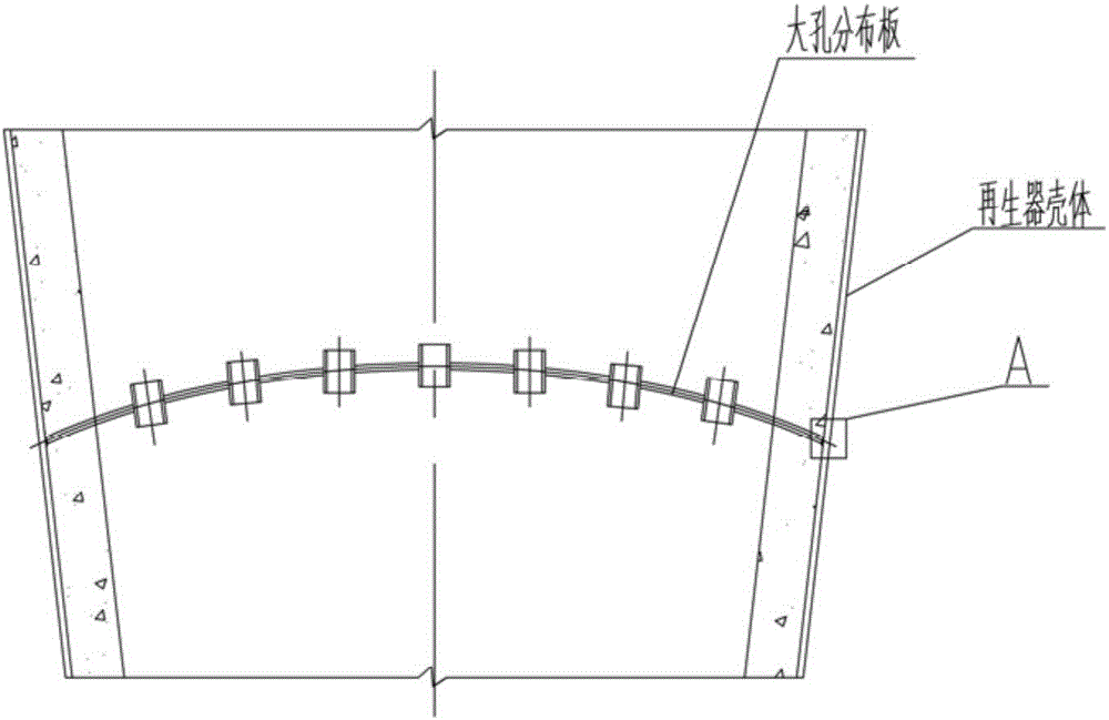
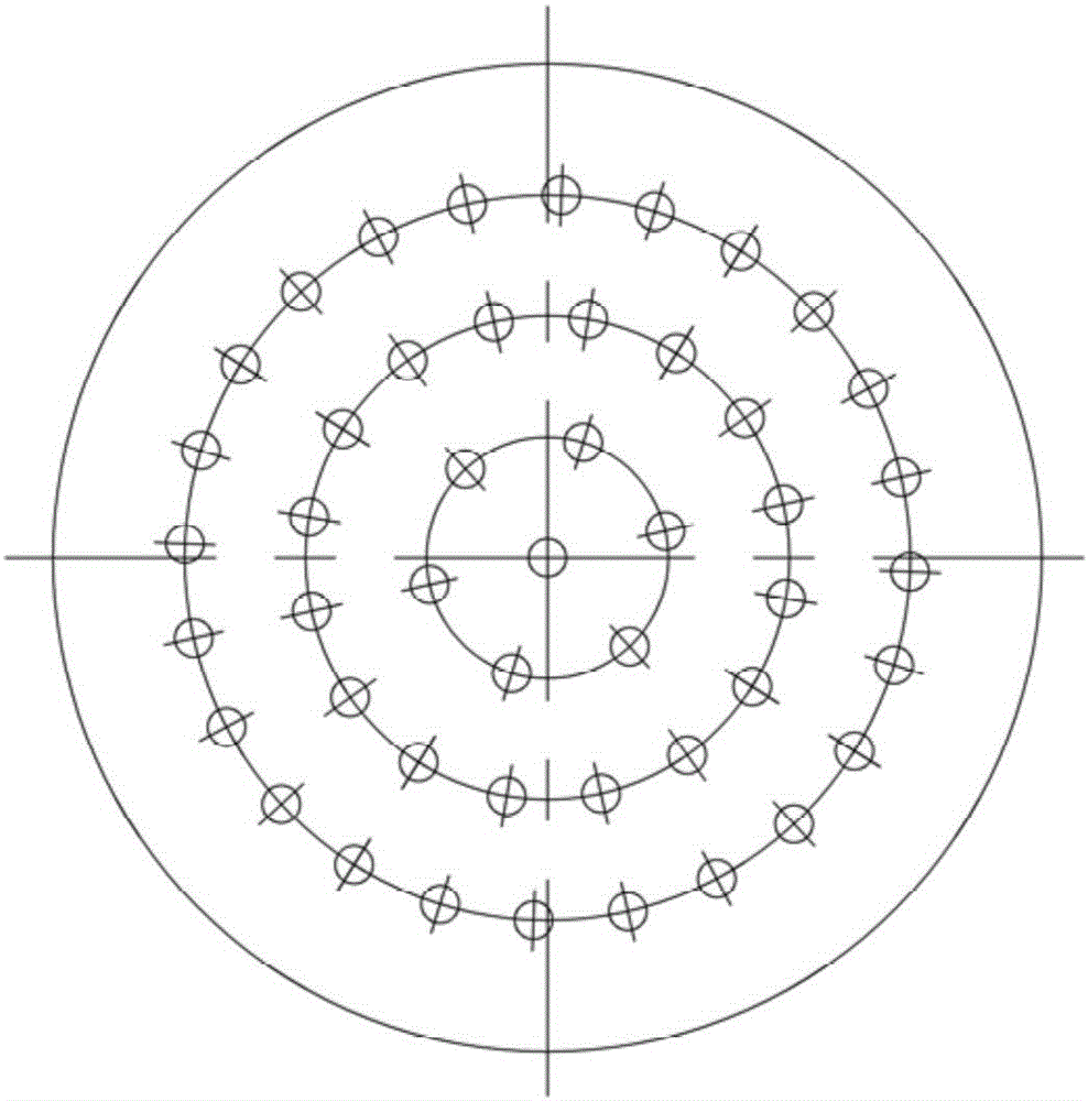
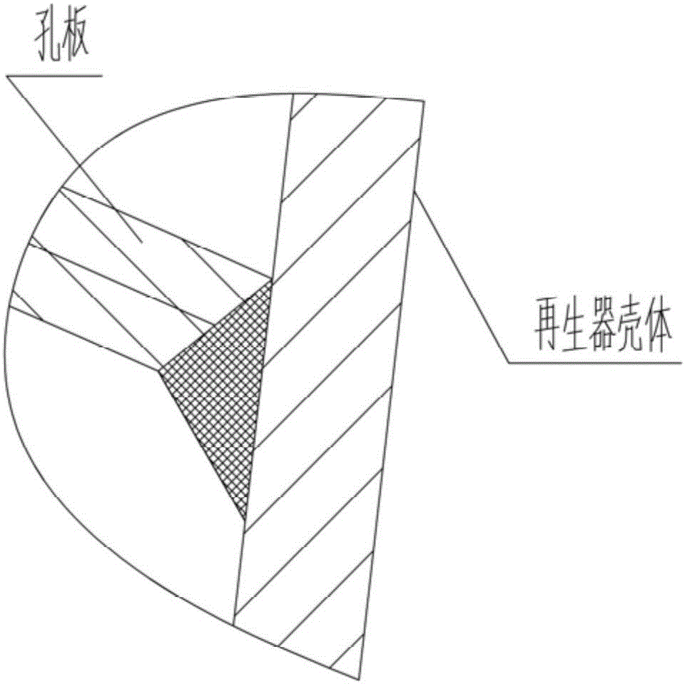
technical field [0001] The invention relates to a second regenerator in a catalytic cracking unit of a refinery, in particular to a regenerator orifice plate structure of a catalytic cracking unit. Background technique [0002] The second regenerator in the catalytic cracking unit is a very important equipment in the oil refining process. Its main function is to further burn off the coke on the catalyst from the first regenerator to restore the activity of the catalyst. The "big hole distribution plate" is an important part of it, and its function is to make the bottom-up catalyst distribution in the second regenerator more uniform, and evenly contact with the air to burn, so as to restore the activity better. [0003] Figure 1-3 It is a schematic diagram of the orifice plate structure of the regenerator of the catalytic cracking unit in the prior art. The form of the orifice plate in the typical structure of the current industrial application is: a spherical head, which i...

Claims


Application Information

Patent Timeline
IPC IPC(8): C10G11/14
CPCC10G11/14
Inventor 赵芬香
Owner LUOYANG ZHIDA PETROCHEM ENG
Why Eureka
Try Eureka