A vertical vacuum drying device

A vacuum drying device and vertical technology, applied in the direction of non-progressive dryers, heating devices, drying chambers/containers, etc., can solve the problems of high production cost, low heating efficiency, residual material residue, etc., to reduce production costs, Improved production efficiency and high heating efficiency

Active Publication Date: 2018-09-25
贵州省印江县依仁食品有限公司
View PDF12 Cites 0 Cited by
  • Summary
  • Abstract
  • Description
  • Claims
  • Application Information

AI Technical Summary

Problems solved by technology

[0002] In production equipment, drying equipment is a commonly used equipment. The material is placed in a vacuum environment, and the temperature of moisture vaporization is reduced, thereby achieving rapid drying. In the prior art, the Chinese patent No. CN1040341322A discloses a vacuum The rotary drying device includes a vacuum dryer. The vacuum dryer is connected to a condenser and a vacuum pump through pipelines in sequence. The pipeline between the condenser and the vacuum pump is a vacuum pipeline. Both ends of the vacuum dryer are fixed on the frame through rotary joints. , the rotary joint is provided with a steam pipeline and a cold water pipeline, the cylinder of the vacuum dryer is a hollow interlayer, the steam pipeline and the cold water pipeline are connected to the interlayer, and a pressure gauge is installed on the steam pipeline. When using this invention, it is necessary to pass The steam heats the vacuum dryer, the heating is slow, and the heating efficiency is low. The invention does not provide a solution for this; when unloading, due to the adhesiveness of the material itself, the unloading in the vacuum dryer cylinder is not clean, and there are a lot of The remaining material remains, and the production cost is high

Method used


Image

  • A vertical vacuum drying device
  • A vertical vacuum drying device
  • A vertical vacuum drying device

Examples


Embodiment Construction

[0019] The technical solution of the present invention will be further described below in conjunction with the accompanying drawings, but the scope of protection is not limited to the description.

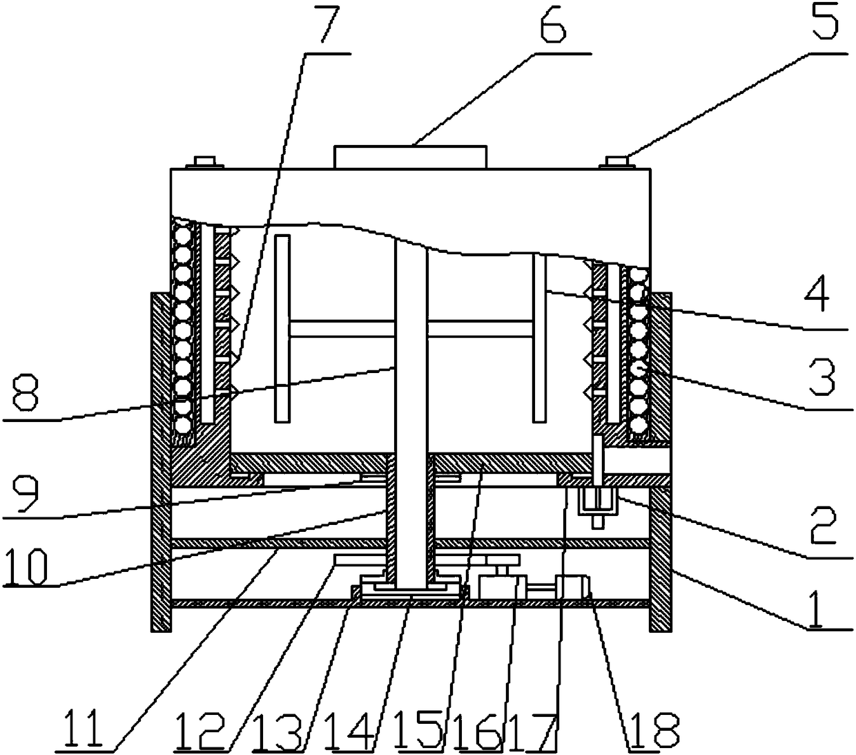
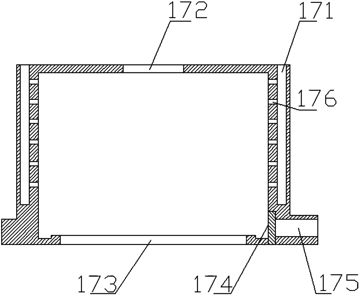
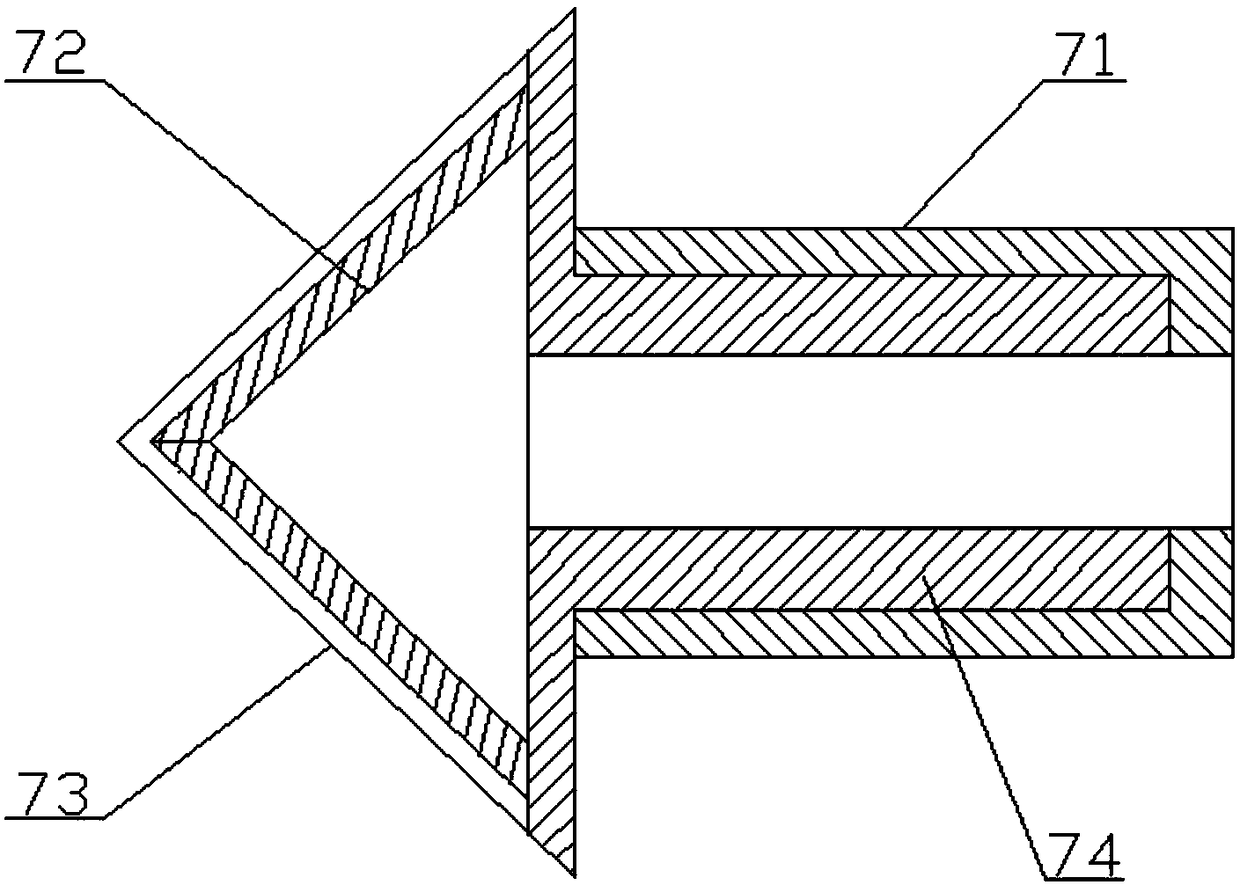
[0020] Such as figure 1 , figure 2 , image 3 A vertical vacuum drying device shown includes a frame 1, a tank body 17, a cover plate 6, a magnetic induction coil 3, a filter tip 7, a rotating shaft 8, a bushing 10, a supporting plate 15, a motor 18 and a supporting plate A11, The tank body 17 is a cylindrical cavity structure, the cover plate 6 is installed on the top surface of the tank body 17, the tank body 17 is vertically installed on the frame 1, and the magnetic induction coil 3 is installed on the tank body 17, the filter tip 7 is installed on the inner wall of the tank body 17, and the stirring blade 4 is installed in the tank body 17, and the stirring blade 4 is installed on the rotating shaft 8, and the rotating shaft 8 is installed on the lining In the sleeve 10, t...


PUM


Abstract

The invention discloses a vertical vacuum drying device. The vertical vacuum drying device comprises a rack, a tank body, a cover plate, magnetic induction coils, filter tips, a rotating shaft, a bushing, a supporting plate, a motor and a support plate A, wherein the tank body is of a cylindrical cavity structure; the cover plate is arranged on the upper top surface of the tank body; the tank body is vertically arranged on the rack; the magnetic induction coils are arranged on the outer wall of the tank body; the filter tips are arranged on the inner wall of the tank body; stirring blades are arranged in the tank body and are also arranged on a rotating shaft; the rotating shaft is arranged in the bushing; the upper end of the bushing is arranged on the supporting plate; the lower end of the bushing is arranged on the support plate A; the supporting plate is arranged on the lower bottom surface of the tank body; a clutch A is arranged between the bushing and the supporting plate; a clutch B is arranged between the bushing and the rotating shaft; the bushing is connected with the motor; and the motor is arranged on the rack. The vertical vacuum drying device disclosed by the invention is high in drying efficiency and low in production cost.

Description

technical field [0001] The invention relates to the technical field of vacuum drying equipment manufacturing, in particular to a vertical vacuum drying device. Background technique [0002] In production equipment, drying equipment is a commonly used equipment. The material is placed in a vacuum environment, and the temperature of moisture vaporization is reduced, thereby achieving rapid drying. In the prior art, the Chinese patent No. CN1040341322A discloses a vacuum The rotary drying device includes a vacuum dryer. The vacuum dryer is connected to a condenser and a vacuum pump through pipelines in sequence. The pipeline between the condenser and the vacuum pump is a vacuum pipeline. Both ends of the vacuum dryer are fixed on the frame through rotary joints. , the rotary joint is provided with a steam pipeline and a cold water pipeline, the cylinder of the vacuum dryer is a hollow interlayer, the steam pipeline and the cold water pipeline are connected to the interlayer, an...

Claims


Application Information

Patent Timeline
Patent Type & Authority Patents(China)
IPC IPC(8): F26B11/14F26B23/08F26B25/04F26B25/12F26B25/02F26B7/00F26B5/04F26B3/347
CPCF26B3/347F26B5/048F26B7/00F26B11/14F26B25/02F26B25/04F26B25/12
Inventor 王小兰
Owner 贵州省印江县依仁食品有限公司
Why Eureka
Try Eureka