
Phase demodulator, optical fiber sound pressure demodulation system, demodulation method and manufacturing method

A technology of phase demodulator and demodulation system, which is applied in the field of sound pressure measurement devices, achieves the effects of high stability, simple structure, and reduced complexity and difficulty

Inactive Publication Date: 2016-11-23
THE HONG KONG POLYTECHNIC UNIV SHENZHEN RES INST
View PDF8 Cites 4 Cited by
  • Summary
  • Abstract
  • Description
  • Claims
  • Application Information

AI Technical Summary

Problems solved by technology

[0004] The purpose of the embodiments of the present invention is to provide a phase demodulator, aiming to solve the above-mentioned problems existing in the existing phase demodulation system

Method used


Image

  • Phase demodulator, optical fiber sound pressure demodulation system, demodulation method and manufacturing method
  • Phase demodulator, optical fiber sound pressure demodulation system, demodulation method and manufacturing method
  • Phase demodulator, optical fiber sound pressure demodulation system, demodulation method and manufacturing method

Examples


Embodiment 1

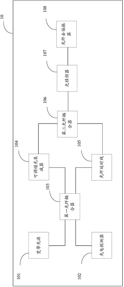
[0038] figure 1 It is a structural block diagram of the phase demodulator 10 provided by the embodiment of the present invention, and is described in detail as follows:

[0039] A kind of phase demodulator 10, adopts the structure of Sagnac fiber optic ring, external diaphragm type optical fiber sound pressure sensor 20, comprises broadband light source 101, photodetector 102, connects described photodetector 102, receives described photodetector 102 The electrical signal of output and the signal analysis module of demodulation, it is characterized in that, described phase demodulator 10 also comprises:

[0040] respectively connecting the broadband light source 101 and the photodetector 102, and splitting the light emitted by the broadband light source 101 into a first optical fiber coupler 103 for clockwise transmission of CW light and counterclockwise transmission of CCW light;

[0041] Connect the first optical fiber coupler 103 to adjust the intensity of the CW light, or...

Embodiment 2

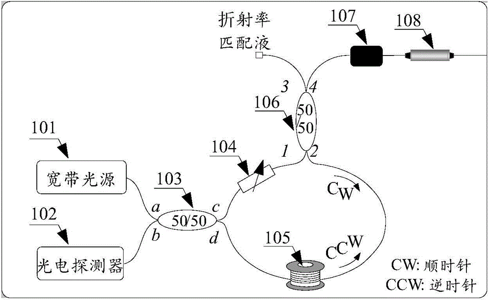
[0083] image 3 It is a better structural diagram of the phase demodulator 10 provided by the embodiment of the present invention, and is described in detail as follows:

[0084] The a port of the first optical fiber coupler 103 is connected to the broadband light source 101, the b port is connected to the photodetector 102, the c port is connected to the first end of the optical fiber delay line 104, and the d port is connected to the tunable optical a first end of the attenuator 105;

[0085] Port 1 of the second fiber coupler 106 is connected to the second end of the fiber delay line 104, port 2 is connected to the second end of the tunable optical attenuator 105, and port 3 is an idle end for antireflection light processing , 4 ports connected to the first end of the optical fiber frequency shifter;

[0086] The second end of the optical fiber frequency shifter is connected to the first end of the optical fiber depolarizer 108 , and the second end of the optical fiber de...

Embodiment 3

[0091] Figure 4 It is a structural block diagram of an optical fiber sound pressure demodulation system provided by an embodiment of the present invention, and is described in detail as follows:

[0092] An optical fiber is used to connect the phase demodulator 10 and the graphene diaphragm-based diaphragm fiber optic acoustic pressure sensor 20 .

[0093] Wherein, the diaphragm-type optical fiber sound pressure sensor 20 is connected to the phase demodulator 10 by an optical fiber, and reflects light through a graphene diaphragm.

[0094] Figure 5 It is a schematic structural diagram of an optical fiber acoustic pressure demodulation system provided by an embodiment of the present invention.

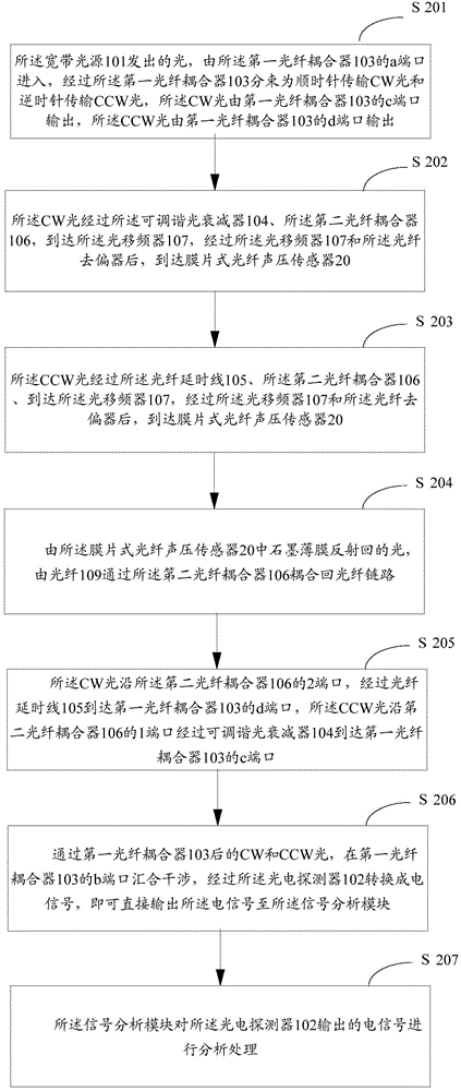
[0095] Figure 6It is an implementation flowchart of a demodulation method based on an optical fiber sound pressure demodulation system provided by an embodiment of the present invention, and is described in detail as follows:

[0096] S601, connecting the diaphragm-type optical f...


PUM


Abstract

The invention, which is suitable for the technical field of the sound pressure measurement device, provides a phase demodulator, an optical fiber sound pressure demodulation system, a demodulation method and a manufacturing method. The phase demodulator employing a Sagnac fiber loop structure comprises a broadband light source, a photoelectric detector, a signal analysis module connected with the photoelectric detector, a first optical fiber coupler connected with the broadband light source and the photoelectric detector, a tunable optical attenuator, a fiber delay line connected with the first optical fiber coupler, a second optical fiber coupler, an optical frequency shifter, and a fiber depolarization device. The tunable optical attenuator connected with the first optical fiber coupler is used for adjusting the intensity of CW light or adjusting the intensity of CCW light; the second optical fiber coupler connected with the fiber delay line and the tunable optical attenuator is used for realizing coupling of light reflected by a membrane type optical fiber sound pressure sensor; the optical frequency shifter connected with the second optical fiber coupler provides stable pi / 2 quadrature phase biasing; and the fiber depolarization device connected with the optical frequency shifter is connected with the membrane type optical fiber sound pressure sensor externally by a fiber. According to the invention, stable phase demodulation of the membrane type optical fiber sound pressure sensor is realized.

Description

technical field [0001] The invention belongs to the technical field of sound pressure measuring devices, and in particular relates to a phase demodulator, an optical fiber sound pressure demodulation system, a demodulation method and a manufacturing method. Background technique [0002] Most of the existing sound pressure demodulation systems use optical fiber Fabry-Perot sensors with simple structure and accurate detection to measure sound pressure, usually including a Fabry-Perot cavity composed of an optical fiber end face and a diaphragm end face. When the air pressure acts on the elastic diaphragm, the diaphragm deforms, thereby changing the cavity length of the Fabry-Perot cavity. By detecting the change of the reflected light interference phase difference caused by the change of the cavity length, the sound pressure measurement can be realized. [0003] However, the existing phase demodulator increases the complexity and difficulty of the sensor demodulation system, a...

Claims


Application Information

Patent Timeline
IPC IPC(8): G01H9/00
Inventor 靳伟马军
Owner THE HONG KONG POLYTECHNIC UNIV SHENZHEN RES INST
Features
  • Generate Ideas
  • Intellectual Property
  • Life Sciences
  • Materials
  • Tech Scout
  • Unparalleled Data Quality
  • Higher Quality Content
  • 60% Fewer Hallucinations
Learn More