Camera lens and electronic device

A camera lens and lens technology, which is applied in the field of camera lenses, can solve the problems of increasing the height of the camera lens and not being able to satisfy the thinning and thinning of personal electronic products, and achieve the effect of reducing the total length and satisfying miniaturization

Active Publication Date: 2018-10-09
GUANGDONG XUYE OPTOELECTRONICS TECH
View PDF8 Cites 0 Cited by
  • Summary
  • Abstract
  • Description
  • Claims
  • Application Information

AI Technical Summary

Problems solved by technology

However, the improvement of the pixels of the camera lens still cannot meet people's increasing requirements for the imaging quality of the camera lens, which will inevitably require more lens elements to improve the imaging quality of the camera lens
However, the increase in lens elements will lead to an increase in the height of the camera lens, which cannot meet the needs of thinner and lighter personal electronic products

Method used


Image

  • Camera lens and electronic device
  • Camera lens and electronic device
  • Camera lens and electronic device

Examples


Embodiment 1

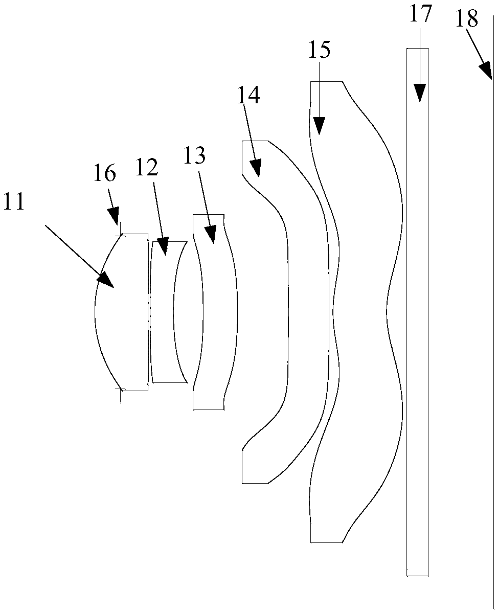
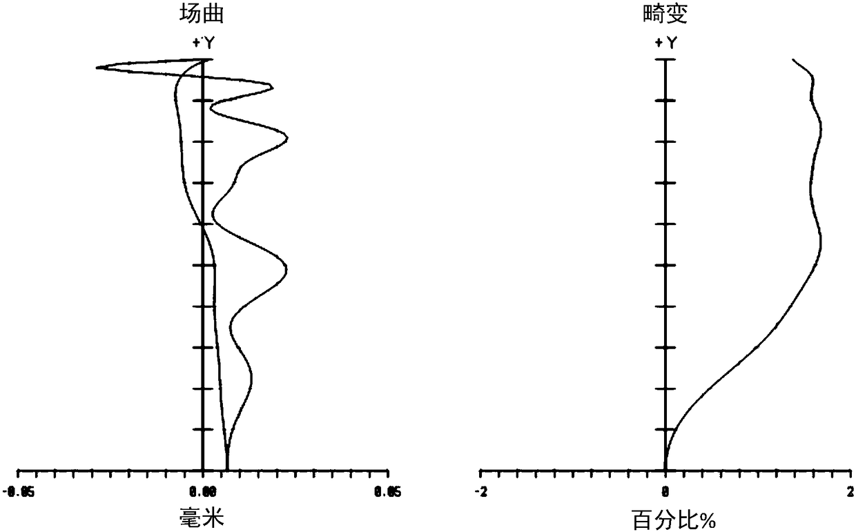
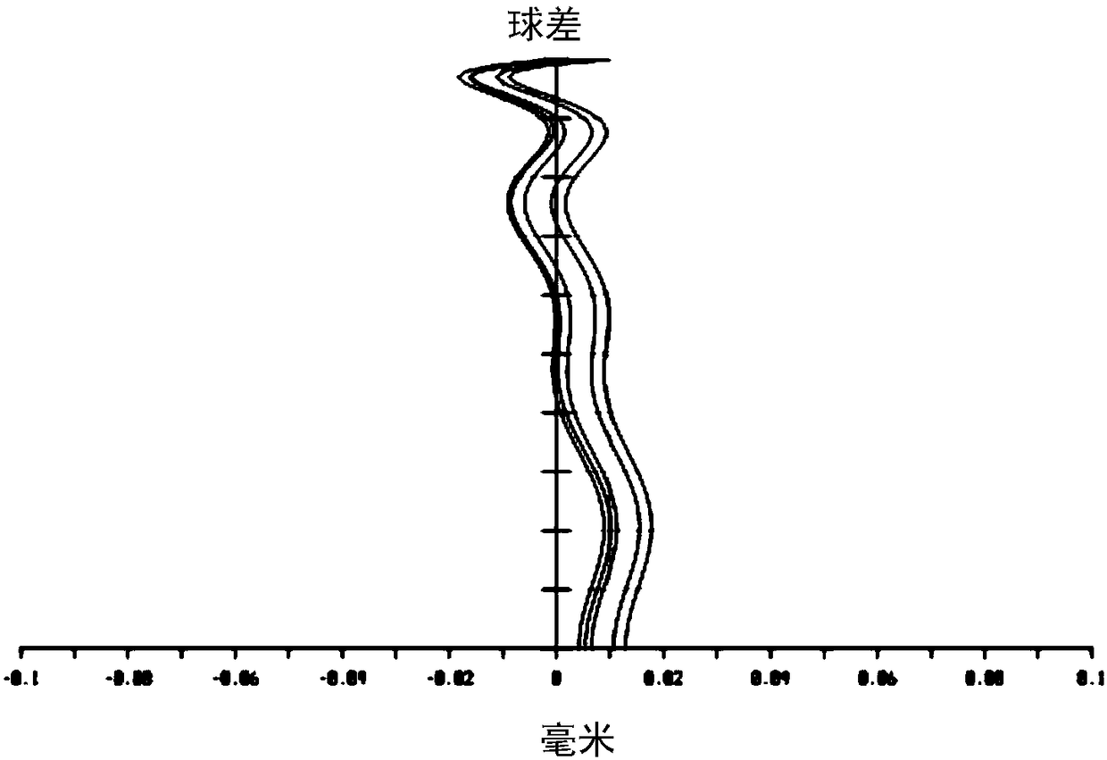
[0083] In this embodiment, the structure of the imaging lens including the first lens 11 to the fifth lens 15, the aperture 16 and the filter 17 is as follows: figure 1 As shown, the field curvature and distortion curves are shown as figure 2 As shown, the spherical aberration curve is shown as image 3 shown.

[0084] Wherein, the specific parameters of the first lens 11 to the fifth lens 15, the aperture 16 and the optical filter 17 refer to Table 1-1, and the specific parameters of the aspheric surfaces of the first lens 11 to the fifth lens 15 are shown in Table 1-2 . In Table 1-1 and Table 1-2, Surface 2 represents the object-side surface of the first lens 11, Surface 3 represents the image-side surface of the first lens 11, Surface 4 represents the object-side surface of the second lens 12, and Surface 5 represents the object-side surface of the first lens 11. The image-side surface of the second lens 12, the object-side surface of the third lens 13 in surface 6, the...

Embodiment approach 2

[0106] In this embodiment, the structure of the imaging lens including the first lens 11 to the fifth lens 15, the aperture 16 and the filter 17 is as follows: Figure 4 As shown, the field curvature and distortion curves are shown as Figure 5 As shown, the spherical aberration curve is shown as Image 6 shown. The specific parameters of the first lens 11 to the fifth lens 15 , the aperture 16 and the filter 17 refer to Table 2-1, and the specific parameters of the aspheric surfaces of the first lens 11 to the fifth lens 15 are shown in Table 2-2.

[0107] table 2-1

[0108]

[0109]

[0110] Table 2-2

[0111]

[0112] Specifically, in this embodiment, TTL / I mgh =1.34, satisfying 1.3mgh <1.5 relational formula;

[0113] |f / f 2 |=0.73, satisfying 0.72 |<0.8 relational expression;

[0114] |f / f 3 |+|f / f 4 |=0.71, satisfying 0.43 |+|f / f 4 |<0.75 relational expression;

[0115] R 10 / f=26.30, satisfying 3.210 The relational expression of / f<30;

[0116] (R ...

Embodiment approach 3

[0128] In this embodiment, the structure of the imaging lens including the first lens 11 to the fifth lens 15, the aperture 16 and the filter 17 is as follows: Figure 7 As shown, the field curvature and distortion curves are shown as Figure 8 As shown, the spherical aberration curve is shown as Figure 9 shown. The specific parameters of the first lens 11 to the fifth lens 15 , the aperture 16 and the filter 17 refer to Table 3-1, and the specific parameters of the aspheric surfaces of the first lens 11 to the fifth lens 15 are shown in Table 3-2.

[0129] Table 3-1

[0130]

[0131] Table 3-2

[0132]

[0133]

[0134] Specifically, in this embodiment, TTL / I mgh =1.36, satisfying 1.3mgh <1.5 relational formula;

[0135] |f / f 2 |=0.74, satisfying 0.72 |<0.8 relational expression;

[0136] |f / f 3 |+|f / f 4 |=0.44, satisfying 0.43 |+|f / f 4 |<0.75 relational expression;

[0137] R 10 / f=13.65, satisfying 3.210 The relational expression of / f<30;

[0138] (R...


PUM


Abstract

The invention provides a camera lens and electronic equipment. The camera lens comprises first to fifth lenses arranged sequentially along a same optical axis from an object side to an image side, wherein the camera lens is in accordance with following relational expressions:1.3<TTL / Imgh<1.5; 0.7<|f / f2|<0.8; 0.4<|f / f3|+|f / f4|<0.75; 3.2<R10 / f<30; -0.91< / =(R9+R10) / (R9-R10)<0. Therefore, by reasonable setup of parameters of each lens, the total length of the camera lens can be reduced on the premise that high pixel is realized, and the requirement on miniaturization of the camera lens and the electronic equipment is met.

Description

technical field [0001] The present invention relates to the technical field of camera lenses, and more specifically, to a camera lens and electronic equipment. Background technique [0002] With the development of semiconductor technology, the pixel area of ​​the photosensitive element is getting smaller and smaller, and the pixel of the camera lens is getting higher and higher. However, the improvement of the pixels of the camera lens is still unable to meet people's increasing requirements for the imaging quality of the camera lens, which inevitably requires adding more lens elements to improve the imaging quality of the camera lens. However, the increase of lens elements will lead to an increase in the height of the camera lens, which cannot meet the demand for thinner and lighter personal electronic products. Based on this, how to rationally design the structure of the camera lens and the parameters of the internal lenses of the camera lens, under the premise of meeting...

Claims


Application Information

Patent Timeline
Patent Type & Authority Patents(China)
IPC IPC(8): G02B13/00
CPCG02B13/0045
Inventor 林肖怡袁正超兰宾利
Owner GUANGDONG XUYE OPTOELECTRONICS TECH
Why Eureka
Try Eureka