
Integrated high-pressure gas pressure reduction module

A high-pressure gas, integrated technology, applied in the direction of fluid pressure control, instruments, control/regulation systems, etc., can solve the problem that the air tightness of the high-pressure gas system cannot be further improved, the inlet pressure gauge and the outlet pressure gauge cannot be installed, and the impact on the high pressure The problems such as the normal operation of the gas system can be solved to achieve the effect of improving construction efficiency and quality, saving installation space, and compact structure

Active Publication Date: 2016-11-23
常州市汇丰船舶附件制造有限公司
View PDF9 Cites 2 Cited by
  • Summary
  • Abstract
  • Description
  • Claims
  • Application Information

AI Technical Summary

Problems solved by technology

However, the pressure reducing valve group of this structure must adopt two safety valves, which respectively protect the pilot valve and the main pressure reducing valve. Although the safety is improved, the pressure reducing valve group must also be connected to external pipelines and Flanges and other components are connected to the front stop valve and the rear stop valve, and are restricted by the structure of the pressure reducing valve. Not only the inlet pressure gauge and the outlet pressure gauge cannot be installed on the valve body, the degree of integration is not high, and further Improve the airtightness of high-pressure gas systems without minimizing the footprint
Furthermore, the existing pressure reducing valve group can only enter the maintenance and overhaul state after it stops working, and cannot be maintained online, which will affect the normal operation of the high-pressure gas system

Method used


Image

  • Integrated high-pressure gas pressure reduction module
  • Integrated high-pressure gas pressure reduction module
  • Integrated high-pressure gas pressure reduction module

Examples


Embodiment Construction

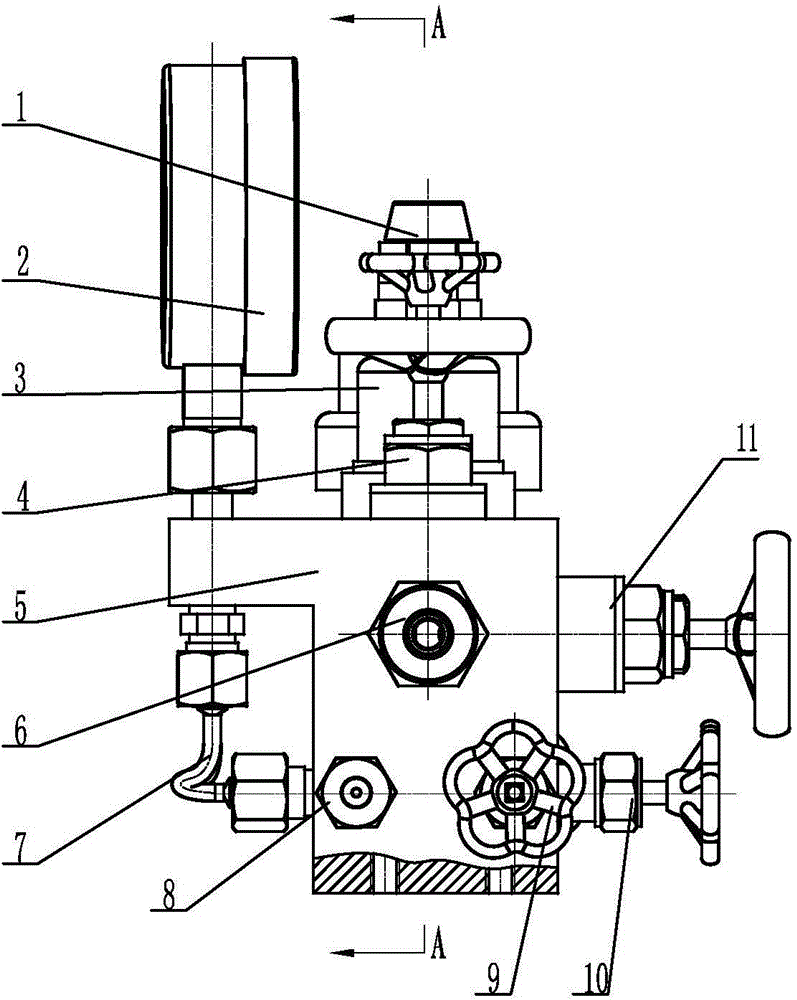
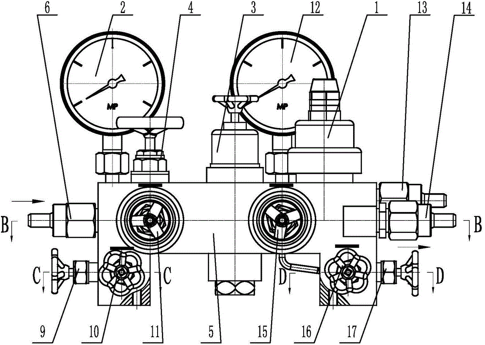
[0031] See Figure 1-8 As shown, the high-pressure gas integrated decompression module of the present invention includes a valve body 5, an intake pressure gauge 2, a front cut-off valve 4, a pressure-reducing valve 3, a safety valve 1, a bypass throttle valve 11 and a rear cut-off valve 15 And outlet pressure gauge 12.

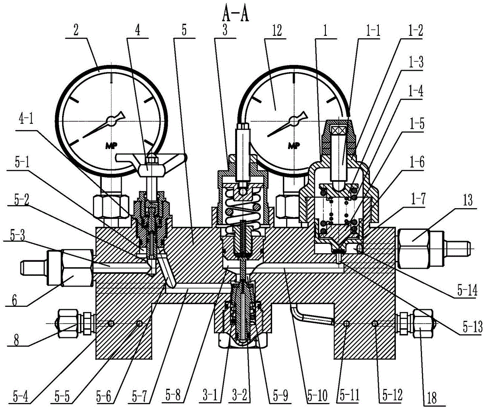
[0032] See Figure 1~4As shown, the valve body 5 of the present invention is provided with an inlet flow passage 5-3, a decompression flow passage 5-10 and an outlet flow passage 5-16, and the inlet flow passage 5-3 passes through the first intermediate flow passage 5-7 and the decompression flow passage. The pressure flow channel 5-10 communicates, and the inlet flow channel 5-3 also communicates with the outlet flow channel 5-16 through the bypass flow channel 5-18, and the decompression flow channel 5-10 passes through the back cut-off valve flow channel 5-19 and The outlet flow passages 5-16 are connected, so the high-pressure gas of the present inventi...


PUM


Abstract

The invention relates to an integrated high-pressure gas pressure reduction module. A valve body is provided with a gas flow incoming channel, a pressure reduction channel and a gas flow outgoing channel. The gas flow incoming channel is communicated with the pressure reduction channel through a first middle channel and is communicated with the gas flow outgoing channel through a bypass channel. The pressure reduction channel is communicated with the gas flow outgoing channel through a rear stop valve channel. An incoming gas pressure gauge, an outgoing gas pressure gauge, a front stop valve and a rear stop valve are mounted on the valve body. A pressure reduction valve is mounted, between the front stop valve and the rear stop valve, on the valve body, and a main valve disc of the pressure reduction valve is corresponding to the end surface of a valve port of the valve body. A safety valve is mounted, behind the pressure reduction valve, on the valve body, and a safety valve pressure release joint mounted on the valve body is communicated with a safety pressure release channel. A bypass throttle valve is mounted on the valve body, and a valve stem of the bypass throttle valve is corresponding to a bypass channel. The integrated high-pressure gas pressure reduction module is simple and reasonable in structure, high in integration, small in size and high in safety; and the pressure reduction valve can be maintained and repaired when a high-pressure gas system works normally.

Description

technical field [0001] The invention relates to a high-pressure gas integrated decompression module, which belongs to the technical field of high-pressure gas decompression. Background technique [0002] For high-pressure gas with an inlet pressure of about 3-20MPa, it usually needs to be decompressed to a working pressure of 0.5-15Kpa through a pressure reducing valve group. However, the existing pressure reducing valve group is formed by connecting the pressure reducing valve, globe valve and safety valve through pipelines. However, since each valve needs to be connected and installed on site through various pipelines, it is not only inconvenient to install, but also has low installation efficiency. But also increased the installation cycle. In addition, because most of the valves need to be connected by pipes, the assembled pressure reducing valve group takes up a large space, has a loose structure, and has low airtightness. At present, the relatively advanced pressure ...

Claims


Application Information

Patent Timeline
Patent Type & Authority Applications(China)
IPC IPC(8): G05D16/00
Inventor 曹毅骆成汉贺志龙吴鸿钧
Owner 常州市汇丰船舶附件制造有限公司
Features
  • Generate Ideas
  • Intellectual Property
  • Life Sciences
  • Materials
  • Tech Scout
  • Unparalleled Data Quality
  • Higher Quality Content
  • 60% Fewer Hallucinations
Learn More