
Camera mounting position calibration method based on plane mirror

A technology of installation position and calibration method, which is applied in the field of photogrammetry, can solve the problems of high price, high cost of use, and low spatial resolution, and achieve simple and convenient results

Active Publication Date: 2016-11-23
BEIHANG UNIV
View PDF2 Cites 8 Cited by
  • Summary
  • Abstract
  • Description
  • Claims
  • Application Information

AI Technical Summary

Problems solved by technology

This method requires the auxiliary camera to have a large field of view, resulting in a relatively low spatial resolution, which affects the calibration accuracy
The auxiliary camera in the above calibration process can use total station, laser tracker and theodolite, etc. These high-precision three-dimensional measurement equipment are expensive and costly to use, which is not conducive to large-scale promotion and use

Method used


Image

  • Camera mounting position calibration method based on plane mirror
  • Camera mounting position calibration method based on plane mirror
  • Camera mounting position calibration method based on plane mirror

Examples


Embodiment

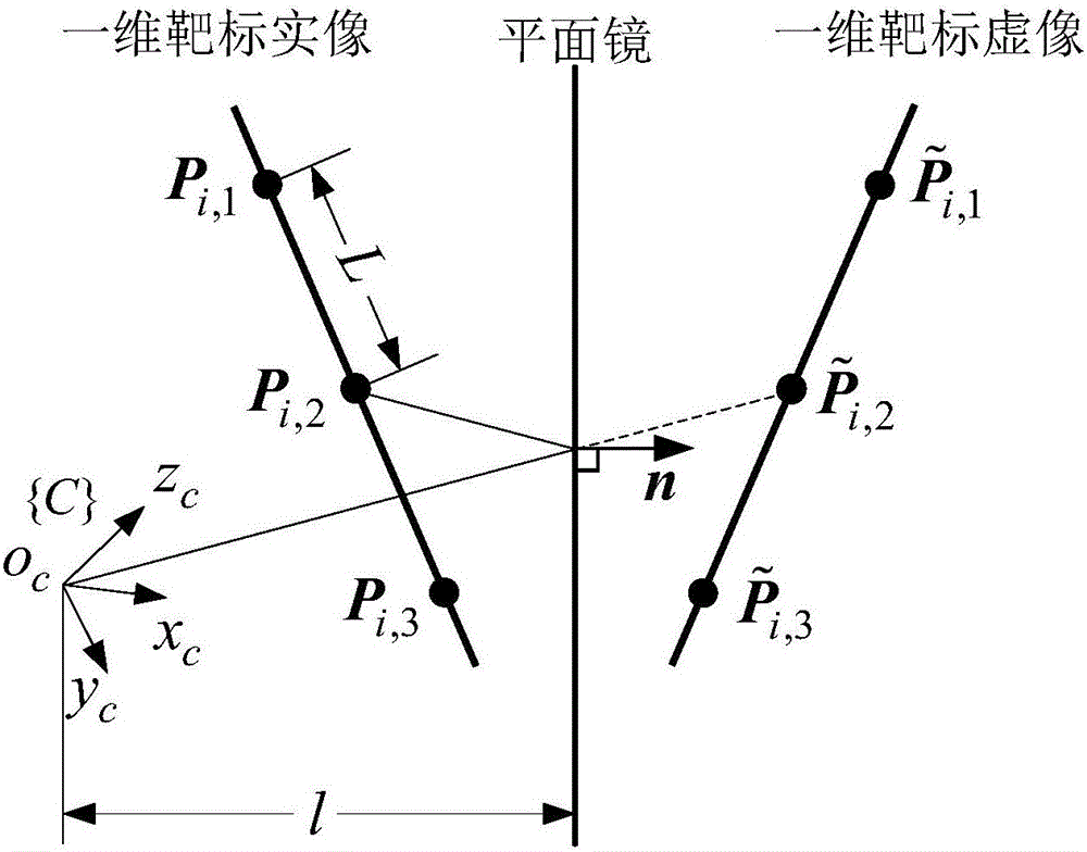
[0082] Mirror pose measurement is a key step in camera installation parameter calibration. In-camera parameter f x = f y =995.556,u 0 = 512 pixels, v 0 =384 pixels, the image resolution is 1024 pixels×768 pixels. Mirror plane normal vector n=[-0.5,0,0.866] T , the distance from the mirror plane to {C} is l=400mm, and the distance between adjacent feature points is L=25mm.

[0083] Define the mirror normal vector error E n , the distance error E from the mirror surface to the optical center l and the reprojection error E q :

[0084] E n = arccos ( n T n g ) ...


PUM


Abstract

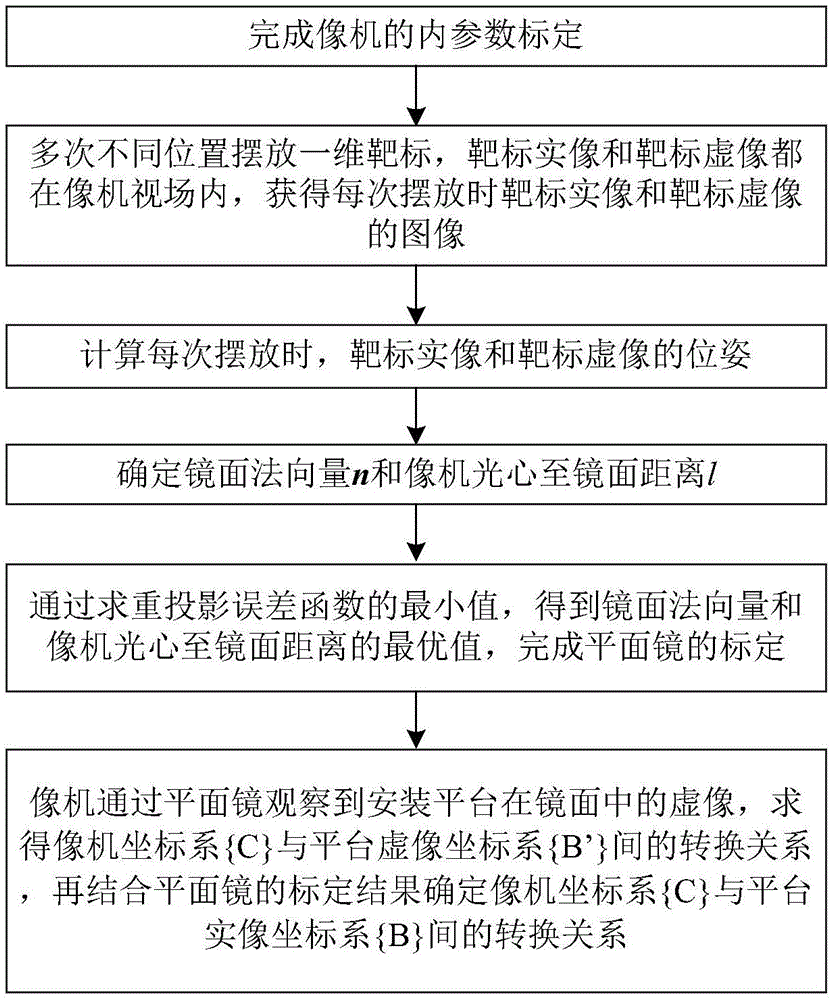
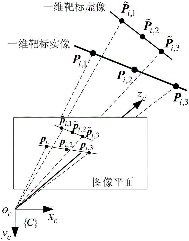
The invention discloses a camera installation position calibration method based on a plane mirror, and belongs to the technical field of photogrammetry of optical systems. The present invention includes the following steps: placing the one-dimensional target in front of the camera for several times, calculating the initial value of the pose of the one-dimensional target in the camera coordinate system according to the cross-ratio invariance, and obtaining the target position by minimizing the reprojection error The optimal solution of the pose of the plane mirror; the closed-form solution method is used to calculate the mirror normal vector and the distance from the optical center of the camera to the mirror; then the optimal solution of the plane mirror pose is obtained by minimizing the reflection and reprojection error; when the mirror pose is determined, combined with the camera The conversion relationship between the coordinate system and the platform virtual image coordinate system is obtained, and the conversion relationship between the camera coordinate system and the platform real image coordinate system is obtained, and the calibration of the camera installation parameters is completed. The present invention does not need to know the target motion and the attitude information of the camera in advance, and the attitude of the mirror surface can be obtained by placing the position at least twice, which is simple and convenient to realize, and is especially suitable for the occasion where the camera and the mirror surface are in fixed positions.

Description

technical field [0001] The invention belongs to the technical field of photogrammetry of optical systems, in particular to a method for measuring the installation position of a camera. Background technique [0002] In the application of visual measurement, what the camera directly measures is the pose of the target in the camera coordinate system. However, many measurement tasks are to measure the relative pose of the target and the platform where the camera is located. The installation position of the camera is calibrated, so that the information of the target in the camera coordinate system is transformed into the platform coordinate system. In many applications, the platform on which the camera is located is not within the field of view of the camera, so the camera cannot directly observe the platform on which it is located. [0003] In addition, camera installation position calibration methods include hand-eye calibration method, full field of view method, etc. The ful...

Claims


Application Information

Patent Timeline
IPC IPC(8): G06T7/00
Inventor 吴晓龙吴森堂
Owner BEIHANG UNIV
Learn More