Miniature waveguide filter

A waveguide filter and waveguide technology, applied in waveguide devices, electrical components, circuits, etc., can solve the problems of volume and weight restrictions, and achieve the effect of improving the degree of miniaturization

Active Publication Date: 2016-11-23
储鹏
View PDF5 Cites 5 Cited by
  • Summary
  • Abstract
  • Description
  • Claims
  • Application Information

AI Technical Summary

Problems solved by technology

[0002] Due to its advantages of low loss, high quality factor, high power capacity, good mechanical characteristics and temperature characteristics, waveguide filters are widely used in

Method used


Image

  • Miniature waveguide filter
  • Miniature waveguide filter
  • Miniature waveguide filter

Examples


Example Embodiment

[0027] Example one:

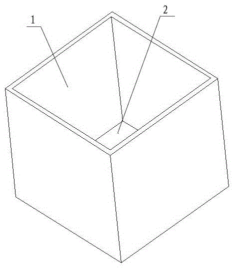
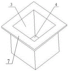
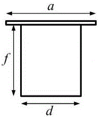
[0028] The present invention provides a miniaturized waveguide resonator. A single concave structure body is embedded in a single waveguide body to form a miniaturized waveguide resonator, such as Figure 1-7 As shown, the external dimensions of the miniaturized waveguide resonator are a=29.2mm, b=29.2mm, c=29.2mm, and the metal thickness is 1mm. The recessed structure is located at the center of the upper surface of the waveguide, d=21.2mm, e=21.2mm , F=24.2mm, d1=5mm, d2=5mm, d3=5mm, d4=5mm, d5=3mm. The resonant frequency of the main mode of the miniaturized waveguide resonator is reduced from 7.8GHz of the conventional waveguide resonator before adding the recessed structure to 2.394GHz after adding the recessed structure. If the conventional waveguide resonator without the recessed structure is used to achieve the main mode resonance of 2.394GHz For frequency, the external dimensions need to be larger as a=90.3mm, b=90.3mm, and c=90.3mm. Compared with ...

Example Embodiment

[0029] Embodiment two:

[0030] The present invention provides a miniaturized waveguide filter, such as Figure 8 As shown, two miniaturized waveguide resonators are combined by nesting to form a second-order filter, and the coupling between miniaturized waveguide resonators is realized by opening a coupling window on the bonding part of the nested structure, input and output ports The feed is directly completed by the probe; the frequency response of the miniaturized waveguide filter is as Picture 9 As shown, the center frequency is 2GHz, the bandwidth is about 0.19GHz, and the outer maximum size of the miniaturized waveguide filter is only 36×36×51mm 3 .

Example Embodiment

[0031] Embodiment three:

[0032] The present invention provides a miniaturized waveguide filter, such as Picture 10 As shown, three miniaturized waveguide resonators are combined by nesting to form a third-order filter, and the coupling between the miniaturized waveguide resonators is realized by opening a coupling window on the bonding part of the nested structure, input and output ports The feed is directly completed by the probe; the frequency response of the miniaturized waveguide filter is as Picture 11 As shown, the center frequency is 2.6GHz, and the bandwidth is about 0.22GHz. There is a transmission zero at 2.3GHz to effectively improve the lower sideband selectivity. The outer maximum size of the miniaturized waveguide filter is only 25×25×34.8mm. 3 .


PUM


Abstract

The invention discloses a miniature waveguide filter. The miniature waveguide filter comprises a waveguide body and a concave structure body, wherein the waveguide body is of an integral structure, and comprises a waveguide side wall and a waveguide bottom part; the concave structure body is of an integral structure, and comprises a concave structure side wall and a concave structure bottom part; the single concave structure body is embedded into the single waveguide body to form a miniature waveguide resonator with a hollow concave structure; a plurality of miniature waveguide resonators with different volumes are mutually embedded to form a miniature waveguide filter body through the hollow concave structures; the attaching part of the embedded miniature waveguide resonators is provided with a coupling window; the miniature waveguide filter body is provided with an input and output port. The miniature waveguide filter has the advantages that the miniature effect of waveguide filter is realized; the volume and weight of waveguide filter are effectively reduced.

Description

Technical field: [0001] The invention relates to a waveguide filter in the field of electromagnetic field and microwave technology, in particular to a miniaturized waveguide filter. Background technique: [0002] Waveguide filters are widely used in various occasions with high performance requirements due to their low loss, high quality factor, high power capacity, good mechanical characteristics and temperature characteristics, but their huge volume and weight are also This limits its application in the field of modern integrated microwave and millimeter wave circuits. Summary of the invention: [0003] In view of the above problems, the technical problem to be solved by the present invention is to provide a miniaturized waveguide filter. [0004] A miniaturized waveguide filter of the present invention includes a waveguide body and a recessed structure body. The waveguide body is an integrated structure including a waveguide sidewall and a waveguide bottom. The recessed structure...

Claims


Application Information

Patent Timeline
IPC IPC(8): H01P1/207
CPCH01P1/207
Inventor 储鹏
Owner 储鹏
Why Eureka
Try Eureka