Wireless power transmission coil device based on meta-material

A wireless energy transmission and coil device technology, applied in circuit devices, loop antennas with ferromagnetic material cores, circuits, etc., can solve the problems of limited application occasions, bulky devices, and additional plates, and achieve significant enhancement effects and structural Compactness, enhanced mutual inductance and magnetic coupling effects

Inactive Publication Date: 2016-11-23
SHANGHAI JIAO TONG UNIV
View PDF3 Cites 4 Cited by
  • Summary
  • Abstract
  • Description
  • Claims
  • Application Information

AI Technical Summary

Problems solved by technology

However, this approach also has certain limitations
In order to achieve a longer transmission distance, it is usually necessary to further increase the thickness of the plate, making the device more bulky
Moreover, the plate is usually placed in the middle of the two coils. When the plate is close to the coil, the effect will be significantly weakened due to over-coupling, which greatly limits its application.

Method used


Image

  • Wireless power transmission coil device based on meta-material
  • Wireless power transmission coil device based on meta-material
  • Wireless power transmission coil device based on meta-material

Examples


Embodiment 1

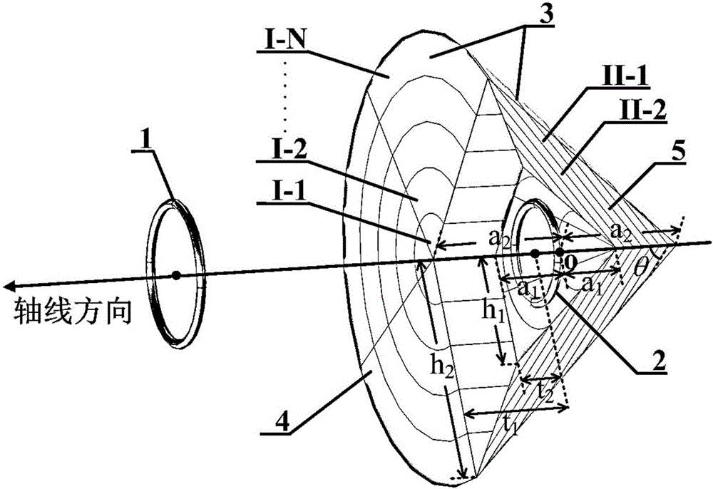
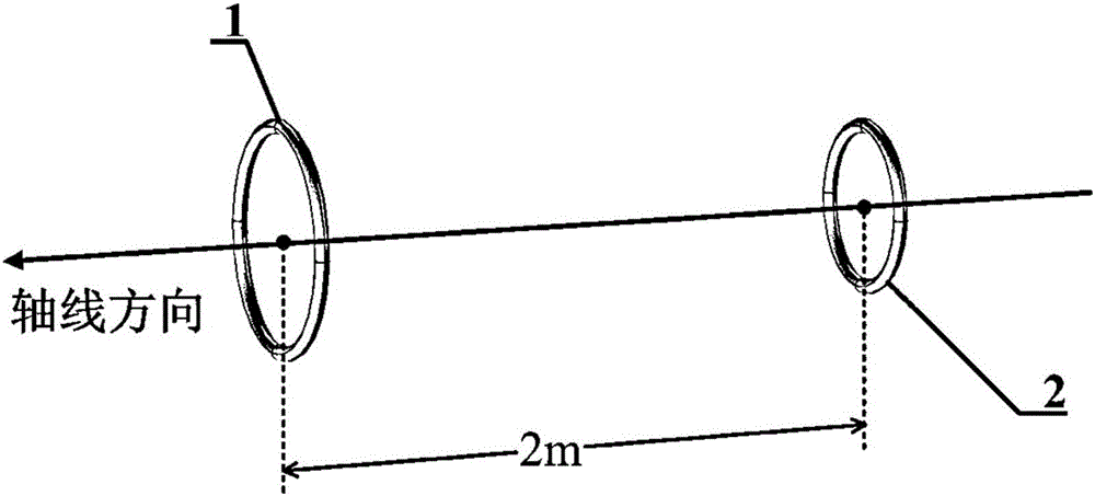
[0060] Such as figure 1 As shown, this embodiment provides a metamaterial-based wireless power transmission coil device, including a transmitting coil, a receiving coil, and a conical displacement medium shell. The radius of the transmitting coil and the receiving coil are both 0.2m, the radius of the coil section is 0.02m, and the number of turns of the coil is 1; the transmitting coil is placed inside the conical displacement medium shell, and the center point of the shell The distance between (origin O) and the receiving coil is 2m, and the size of the conical displacement medium shell is a 1 = 0.3m, a 2 = 0.6m, h 1 = 0.5m, h 2 =1m, such as figure 1 As shown, the designed displacement distance d is 0.9m, and the calculated magnetic permeability of the bottom and side shells is shown in Table 1. The bottom shell is divided into 5 layers, and the thickness of each layer is 0.2m. The side shell is arranged alternately with 10 layers of II-1 and 10 layers of II-2, and the ...

Embodiment 2

[0068] The metamaterial-based wireless power transmission coil device in this embodiment includes a transmitting coil, a receiving coil, and a conical displacement medium shell, and the receiving coil is placed inside the conical displacement medium shell. Other parameters are all the same as in Example 1.

[0069] For the above parameters, using the metamaterial-based wireless power transmission coil device provided in Example 2, the mutual inductance between the transmitting coil and the receiving coil is about 1.86nH, and the magnetic field intensity distribution is as follows Figure 8 shown.

[0070] It can be seen that the mutual inductance of the transmitter coil and the receiver coil increases by 2.76 times compared with the traditional wireless power transmission coil device using the metamaterial flat plate; Compared with the traditional wireless power transmission coil device, the center of the magnetic field generated by the transmitting coil shifts to the left, a...


PUM


Abstract

The invention provides a wireless power transmission coil device based on meta-material, the device comprises a transmitting coil, a receiving coil and a conical displacement medium shell, and the conical displacement medium shell wraps the transmitting coil or the receiving coil in an air chamber of the shell; the distance between the transmitting coil and the receiving coil is greater than the diameters of the transmitting coil and the receiving coil separately; the conical displacement medium shell comprises a bottom shell and a side shell; and the bottom shell and the side shell respectively comprises various kinds of uniform and isotropous magnetic material layers. The conical displacement medium shell can optically moves a coil in the air chamber to a specified position on the outside of the shell, that is, the relative position between the transmitting coil and the receiving coil can be changed, so that the mutual inductance and the magnetic coupling of the transmitting coil and the receiving coil can be substantially enhanced.

Description

technical field [0001] The invention relates to the field of electromagnetic design and wireless power transmission technology, in particular to a wireless power transmission coil device based on metamaterials (which can effectively enhance the magnetic coupling effect). Background technique [0002] In recent years, the increasing demand for wireless power transfer technology in consumer electronics, electric vehicles, and implanted medical devices has greatly promoted the research and development of this technology. Enterprises in the field have joined in the research of this technology. This technology involves many aspects such as power electronic circuit, coil electromagnetic design, automatic control, communication protocol, among which coil electromagnetic design is particularly important. Metamaterials are materials with negative permittivity or magnetic permeability and special electromagnetic properties. They do not exist in nature and can only be manufactured art...

Claims


Application Information

Patent Timeline
Patent Type & Authority Applications(China)
IPC IPC(8): H02J50/00H01F38/14H01Q7/06H01Q15/00
Inventor 李雯文姚辰马殿光唐厚君张颖异蔡位焜孙龙钊
Owner SHANGHAI JIAO TONG UNIV
Why Eureka
Try Eureka